Safety belt shrinking device

A technology of retracting device and seat belt, which is applied in the direction of seat belt, belt tensioner, and energy-absorbing device in the vehicle, can solve problems such as breaking of energy-absorbing components.

Inactive Publication Date: 2002-03-06
KK TOKAI RIKA DENKI SEISAKUSHO
View PDF0 Cites 10 Cited by
  • Summary
  • Abstract
  • Description
  • Claims
  • Application Information

AI Technical Summary

Problems solved by technology

However, if such an energy absorbing member is used, since the reel can rotate relative to the lock base, various stresses such as shear stress will conce

Method used


Image

  • Safety belt shrinking device
  • Safety belt shrinking device
  • Safety belt shrinking device

Examples


Embodiment Construction

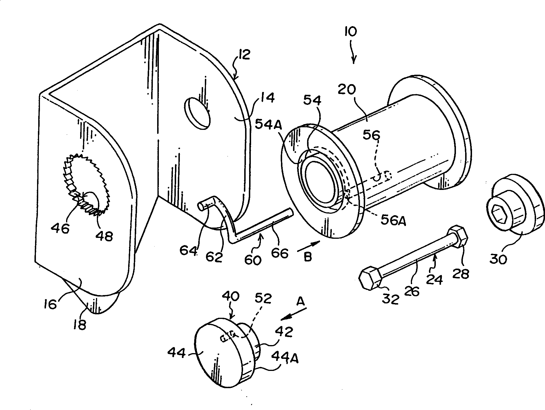
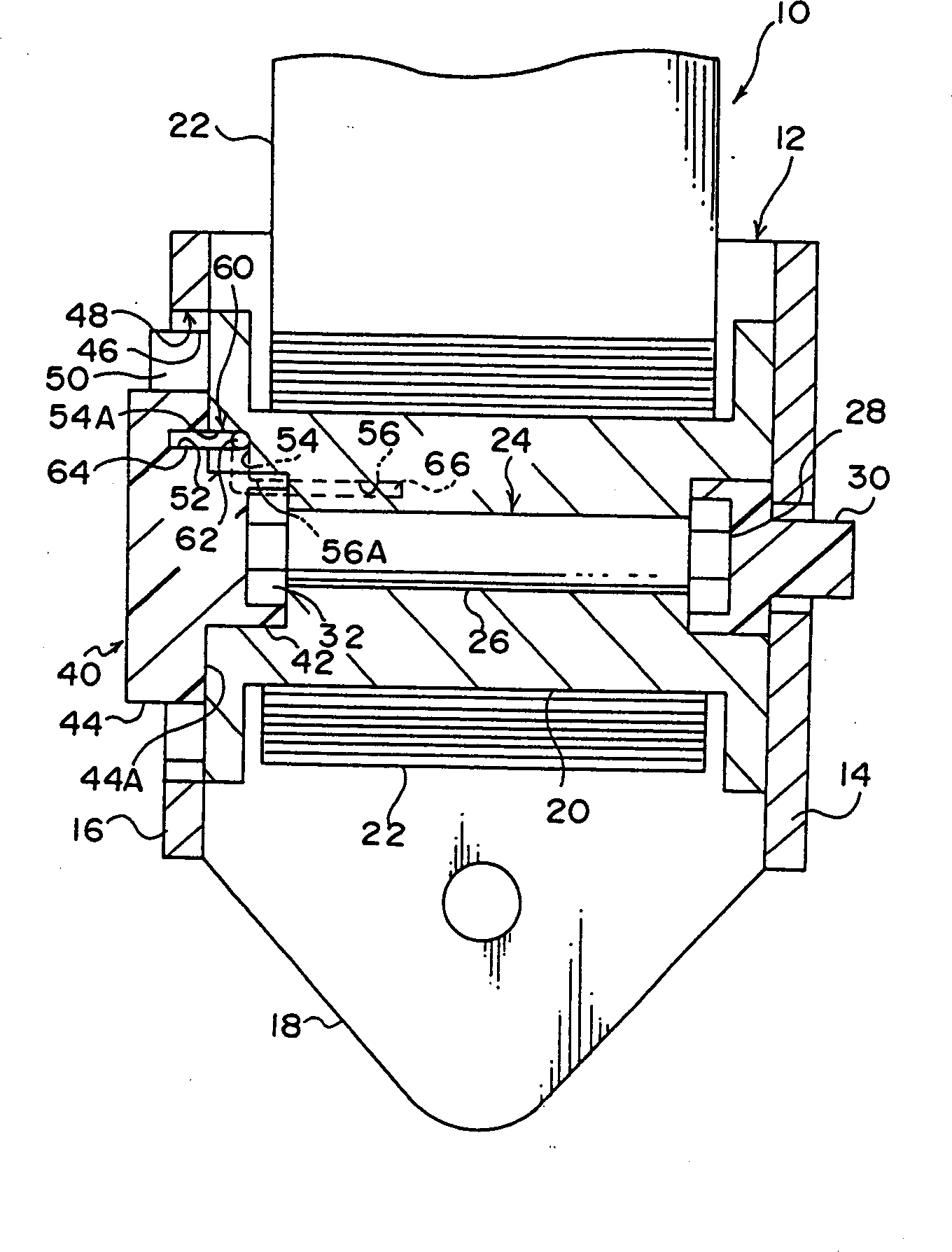
[0018] exist figure 1 In , the structure of the main part of the seat belt retracting device 10 related to the preferred embodiment of the present invention is shown in an exploded perspective view. exist figure 2 , the structure of the seat belt retractor 10 is shown in a front sectional view.

[0019] Such as figure 1 with 2 As shown, the belt retractor 10 has a frame 12 . The frame 12 is formed from a pair of uprights 14 and 16 and a support plate 18 . Both the vertical boards 14 and 16 are plate-like structures, and are arranged relative to each other along the thickness direction. The support plate 18 connects the lateral ends of the vertical plates 14 and 16, and is fixed on one side of the car seat by fastening devices such as bolts. Therefore, from a plan view, the frame 12 as a whole presents a U shape.

[0020] A reel 20 is installed between the vertical plate 14 and the vertical plate 16 of the frame 12, and this reel is used as a tension shaft, and its axia...


PUM


Abstract

A webbing retractor having a force limiter mechanism whose energy absorption amount is large and which can reliably absorb energy. To this end, a wire is provided as an energy absorbing member having a fixing portion, a curved portion and a fit-in portion. When a spool rotates in a pull-out direction relative to a lock base, the fit-in portion is forcibly pulled-out from a fit-in hole and deformed while being strongly rubbed. Here, the fit-in portion deforms along an imaginary extended line of the curved portion. Thus, breaking of the wire due to concentration of shearing stress at one portion of the wire can be prevented.

Description

technical field [0001] The invention relates to a retracting device for a safety belt of an automobile. When the automobile decelerates rapidly, the device can tighten the safety belt along the direction of restricting and fixing the occupants in the automobile. Specifically, the present invention is a kind of automobile safety belt retracting device, when the outward stretching action of the automobile safety belt is hindered, the device can make the safety belt stretch out a section of predetermined length (amount), and can absorb energy. Background technique [0002] A car seat belt retractor that forms a seat belt assembly inside a car and is usually equipped with a locking mechanism that locks the spool (i.e., the tensioning shaft) when the car is decelerating rapidly , which in turn prevents the seat belt from stretching outwards. [0003] An example of such a locking mechanism is a locking mechanism with a locking base and a locking device. The locking base is inst...

Claims


Application Information

Patent Timeline
IPC IPC(8): B60R22/28B60R22/34
CPCB60R22/3413B60R2022/286B60R2022/287B60R22/34
Inventor 永田智纪森信二
Owner KK TOKAI RIKA DENKI SEISAKUSHO
Why Eureka
Try Eureka