Spark plug

a technology of spark plugs and spark plugs, which is applied in the field of spark plugs, can solve the problems of degrading ignition performance and worse wear resistance of the fusion portion, and achieve the effects of preventing the degradation of wear resistance or ignition performance, not being excessively large, and reducing the thermal stress differen

Active Publication Date: 2012-02-02
NGK SPARK PLUG CO LTD
View PDF0 Cites 10 Cited by
  • Summary
  • Abstract
  • Description
  • Claims
  • Application Information

AI Technical Summary

Benefits of technology

[0033]According to the spark plug of the configuration 1, the ground electrode has a concave hole portion, and the noble metal chip is bonded to the hole portion of the ground electrode through the fusion portion formed by emitting a laser beam or the like from the side surface thereof. Accordingly, the fusion portion may be suppressed from being exposed to the gap (the spark discharge gap), and degradation of the wear resistance or the ignition performance may be more reliably prevented.
[0034]Further, according to the spark plug of the configuration 1, 70% or more of the bottom surface of the noble metal chip is bonded to the ground electrode. That is, the sufficiently wide fusion portion is interposed between the bottom surface of the noble metal chip and the ground electrode. Accordingly, a difference in the thermal stress generated between the noble metal chip and the ground electrode in accordance with the thermal expansion may be more reliably absorbed by the fusion portion.
[0035]Further, since a gap (space) is formed between the noble metal chip and at least a part of the inner wall surface of the hole portion, the noble metal chip may be thermally expanded toward the side surface thereof at the time of using (heating) the spark plug. Accordingly, a difference in the thermal stress generated between the noble metal chip and the ground electrode may be more reliably reduced.
[0036]On the other hand, since the size of the gap is set to 1.0 mm or less in the direction perpendicular to the central axis of the noble metal chip so as not to become excessively large, heat may be more efficiently transferred from the noble metal chip to the ground electrode. As a result, a difference in the thermal stress generated between the noble metal chip and the ground electrode may be further reduced.
[0037]That is, according to the spark plug of the configuration 1, since the gap is provided, the noble metal chip may be thermally expanded toward its side surface. Since the gap is prevented from becoming excessively large, the heat of the noble metal chip may be efficiently transferred. Accordingly, a difference in the thermal stress between the noble metal chip and the ground electrode may be sufficiently reduced, and a difference in the thermal stress may be effectively absorbed by the comparatively wide fusion portion. As a result, the generation of oxidized scale at the boundary portion between the noble metal chip and the ground electrode may be more reliably prevented, and the peeling resistance of the noble metal chip may be noticeably improved.
[0038]According to the spark plug of the configuration 2, at least a part of a portion located at the opposite side of the exposed surface in the fusion portion is formed to intrude into the body portion of the ground electrode. That is, the edge portion of the fusion portion is held by the body portion. For this reason, the thermal expansion of the fusion portion may be effectively suppressed at the time of using the spark plug, and a difference in the thermal stress generated between the fusion portion and the ground electrode may be reduced. As a result, the generation of oxidized scale between the fusion portion and the ground electrode may be further suppressed, and the peeling resistance may be further improved.

Problems solved by technology

However, the fusion portion has wear resistance worse than that of the noble metal chip.
Further, since a minute uneven portion may be formed on the surface of the fusion portion, a spark discharge is generated between the center electrode and the uneven portion having a comparatively large electrical field strength, so that there is a concern in that ignition performance may be degraded.

Method used


Image

  • Spark plug
  • Spark plug
  • Spark plug

Examples


first embodiment

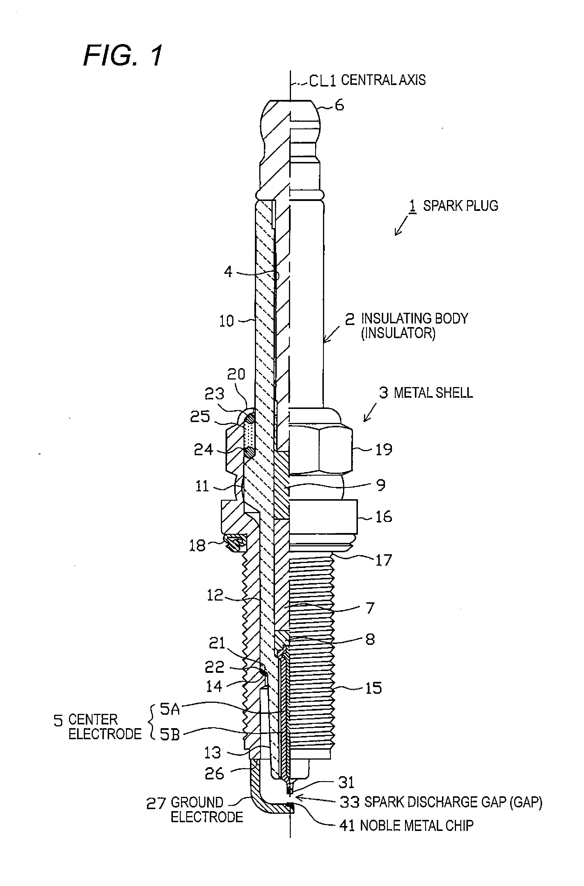
[0063]Hereinafter, an embodiment of the invention will be described by referring to the drawings. FIG. 1 is a partially cutaway front view illustrating a spark plug 1. Further, in FIG. 1, the direction of the central axis CL1 of the spark plug 1 is described as the up / down direction of the drawing, the lower side is described as the leading end side of the spark plug 1, and the upper side is described as the rear end side thereof

[0064]The spark plug 1 includes an insulator 2 which is a cylindrical insulator, a cylindrical metal shell 3 which holds the insulator, and the like.

[0065]As is well known, the insulator 2 is formed by baking alumina or the like at a high temperature, and includes: a rear end side body portion 10 which is formed at the rear end side of the external shape; a large diameter portion 11 which is disposed at the leading end side in relation to the rear end side body portion 10 and protrudes outward in the radial direction; a middle body portion 12 which is dispos...

second embodiment

[0104]Next, a second embodiment will be described on the basis of points different from the first embodiment.

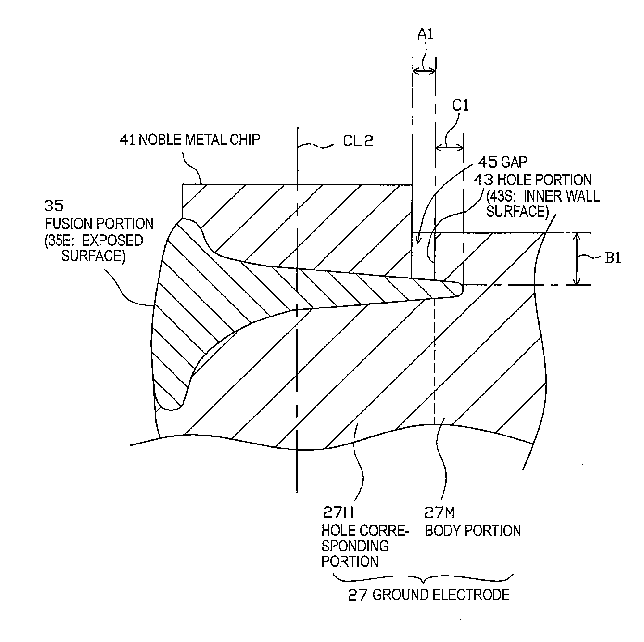
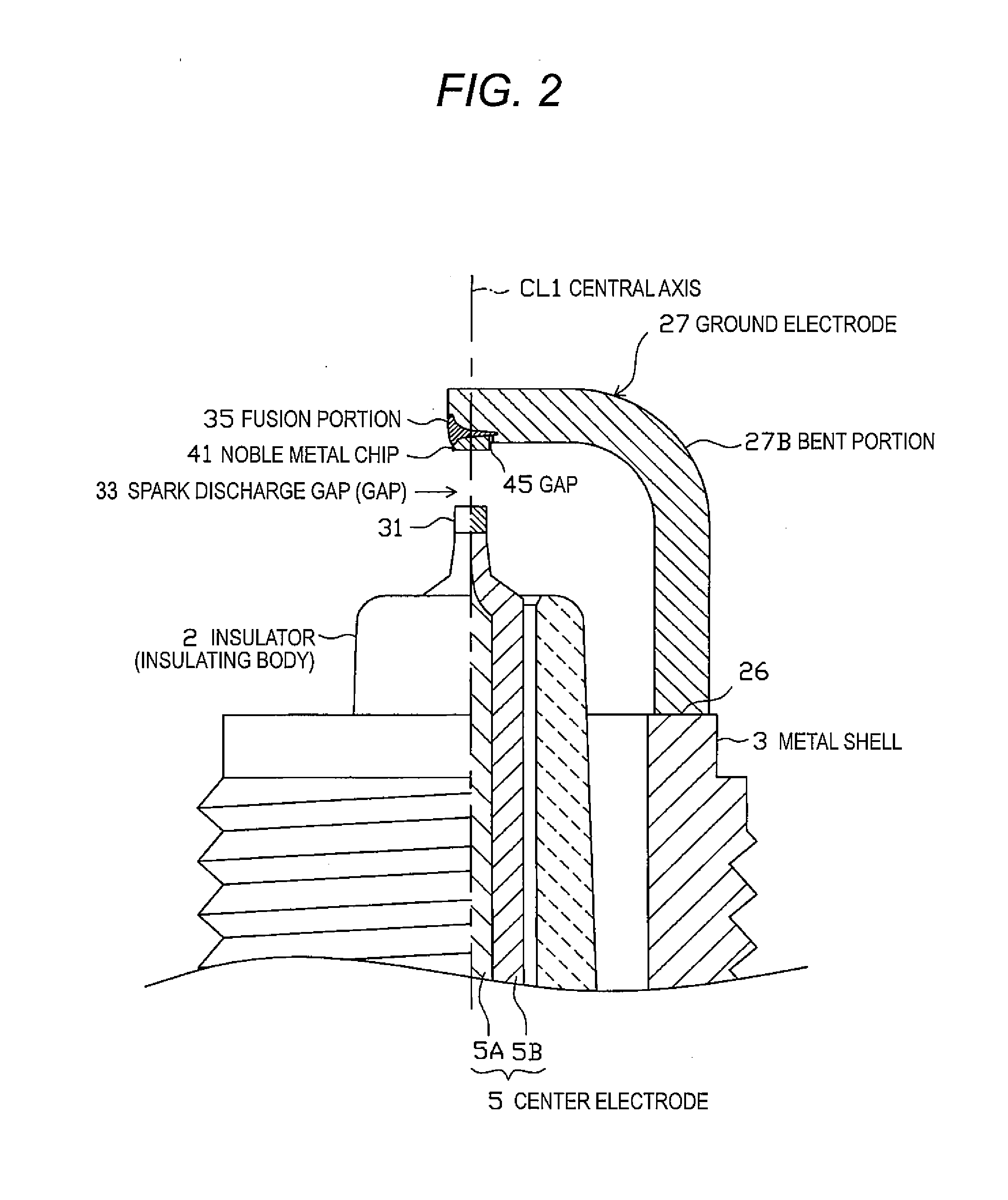
[0105]A spark plug 1A of the second embodiment has a configuration in which a leading end surface of a ground electrode 57 faces the side surface of the center electrode 5 (the noble metal portion 31) as shown in FIG. 5. Then, a concave hole portion 73 is formed in the leading end surface of the ground electrode 57, and a noble metal chip 71 is bonded to the hole portion 73 through a fusion portion 65. The fusion portion 65 is formed by emitting a laser beam or an electron beam from the side surface of the noble metal chip 71 to the side surface of the ground electrode 27.

[0106]Further, a spark discharge gap 77 is formed between the noble metal chip 71 and the side surface of the center electrode 5 (the noble metal portion 31), and a spark discharge is performed in the direction substantially perpendicular to the central axis CL1 in the spark discharge gap 77. That is, the sp...


PUM

PropertyMeasurementUnit
angleaaaaaaaaaa
angleaaaaaaaaaa
curvature radiusaaaaaaaaaa

Abstract

Peeling resistance of a noble metal chip is improved by reducing a difference in the thermal stress generated between the noble metal chip and a ground electrode. A spark plug 1 includes an insulator 2, a center electrode 5, a metal shell 3, and a ground electrode 27, wherein a spark discharge gap 33 is formed between the center electrode 5 and the noble metal chip 41 bonded to the ground electrode 27. The ground electrode 27 is provided with a concave hole portion 43, and 70% or more of the noble metal chip 41 is bonded to the hole portion 43 of the ground electrode 27 through a fusion portion 35 formed by fusing the noble metal chip and the ground electrode 27 to each other by emitting a laser beam or the like from the side surface of the noble metal chip. A gap 45 is formed between the noble metal chip 41 and at least a part of an inner wall surface 43 S of the hole portion 43 so as to be more than 0 mm and equal to or less than 1.0 mm in the direction perpendicular to the central axis CL2 of the noble metal chip 41.

Description

TECHNICAL FIELD[0001]The present invention relates to a spark plug that is used in an internal combustion engine and the like.BACKGROUND ART[0002]A spark plug used in a combustion device such as an internal combustion engine includes, for example, a center electrode that extends in the axial direction, an insulating body that is provided in the outer periphery of the center electrode, a cylindrical metal shell that is assembled to the outside of the insulating body, and a ground electrode that has a base end portion bonded to the leading end portion of the metal shell. The ground electrode is curved at the substantially middle portion thereof so that its leading end portion faces the leading end portion of the center electrode. Accordingly, a spark discharge gap is formed between the leading end portion of the center electrode and the leading end portion of the ground electrode.[0003]Further, in recent years, a technology has been introduced which bonds a noble metal chip to a porti...

Claims


Application Information

Patent Timeline
Patent Type & Authority Applications(United States)
IPC IPC(8): H01T13/32B23K101/00
CPCF02P13/00H01T13/32H01T13/20
Inventor SAKAYANAGI, NOBUAKINAKAYAMA, KATSUTOSHI
Owner NGK SPARK PLUG CO LTD
Why Eureka
Try Eureka