Bone cement mixing and delivery system including a delivery gun and a cartridge having a piston, the delivery gun configured to release the piston

a technology of bone cement and delivery gun, which is applied in the direction of osteosynthesis devices, instruments, prostheses, etc., can solve the problems of low mechanical advantage of advancing drive rod and ram disk, and achieve the effects of reducing the number of steps, facilitating the loading of powder components, and reducing mess

Active Publication Date: 2008-07-01
STRYKER CORP
View PDF108 Cites 52 Cited by
  • Summary
  • Abstract
  • Description
  • Claims
  • Application Information

AI Technical Summary

Benefits of technology

[0010]One advantage of the mixing cartridge is the conveniently positioned locking member used to lock the piston in the distal end. By using the resilient portion to bias the male portion into mating engagement with the female portion, a user can easily release the piston from the locked position by either manually or mechanically acting against the bias of the resilient portion to disengage the male and female portions.
[0012]An advantage of the delivery gun is the use of the linkage system to increase the mechanical advantage needed to successfully advance the drive mechanism and force the bone cement from the cartridge while minimizing fatigue to a user of the delivery gun.
[0013]In one aspect of the delivery gun, the drive mechanism includes a drive rod and gripper plates to advance the drive rod. The gripper plates frictionally engage the drive rod to advance the drive rod when the trigger is actuated. In one embodiment, the gripper plates include mating pegs and notches to align adjacent gripper plates. In another embodiment, the gripper plates are coated to increase lubricity and corrosion resistance thereof.
[0015]A bone cement mixing and delivery system is also provided. The mixing and delivery system includes the cartridge and the delivery gun. In this aspect of the invention, the locking member includes a release button to release the piston from the locked position. At the same time, the delivery gun includes a release mechanism integrated into the drive mechanism to engage the release button. When the cartridge is placed into the cradle of the delivery gun, the drive mechanism is advanced and the release mechanism engages the release button to release the piston from the locked position. This configuration reduces the number of steps typically associated with releasing the piston. By incorporating the release mechanism into the drive mechanism, when the drive mechanism is advanced, the piston is automatically released.
[0016]A bone cement loading system for receiving the liquid and powder components of the bone cement is also provided. The loading system includes the cylinder with the piston locked in the distal end. A base defining a cavity is provided for receiving and securing the distal end of the cylinder. A funnel is provided for coupling to the proximal end of the cylinder to channel the powder component of the bone cement into the mixing chamber. The funnel has a proximal end with an oblong oval-shaped periphery to facilitate loading of the powder component of the bone cement into the mixing chamber and a distal end with a circular periphery for snugly fitting into the proximal end of the cylinder. One particular advantage to this loading system is the use of the oblong oval-shaped funnel. The shape of the funnel reduces any mess typically associated with filling the mixing chamber with powder.

Problems solved by technology

However, in Nic, the trigger directly supports each of the pawl members which results in a low mechanical advantage to advance the drive rod and ram disk.

Method used


Image

  • Bone cement mixing and delivery system including a delivery gun and a cartridge having a piston, the delivery gun configured to release the piston
  • Bone cement mixing and delivery system including a delivery gun and a cartridge having a piston, the delivery gun configured to release the piston
  • Bone cement mixing and delivery system including a delivery gun and a cartridge having a piston, the delivery gun configured to release the piston

Examples


Embodiment Construction

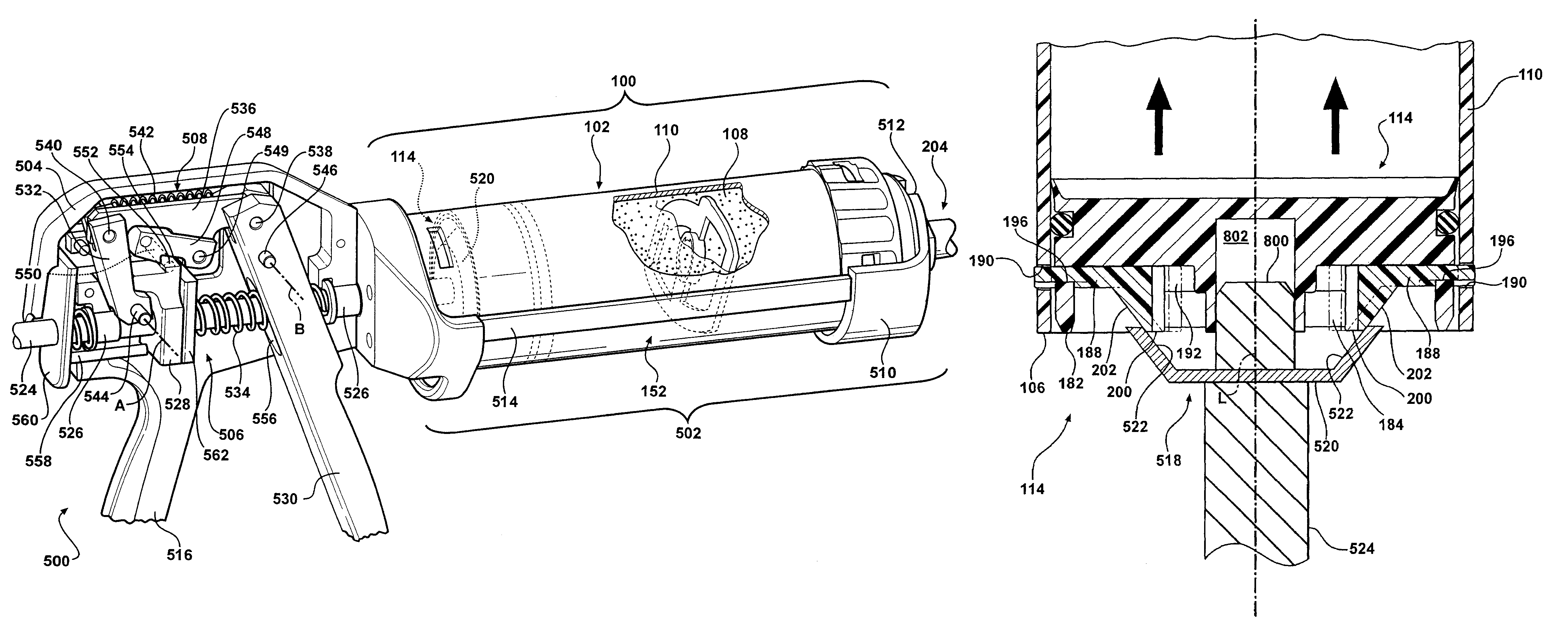
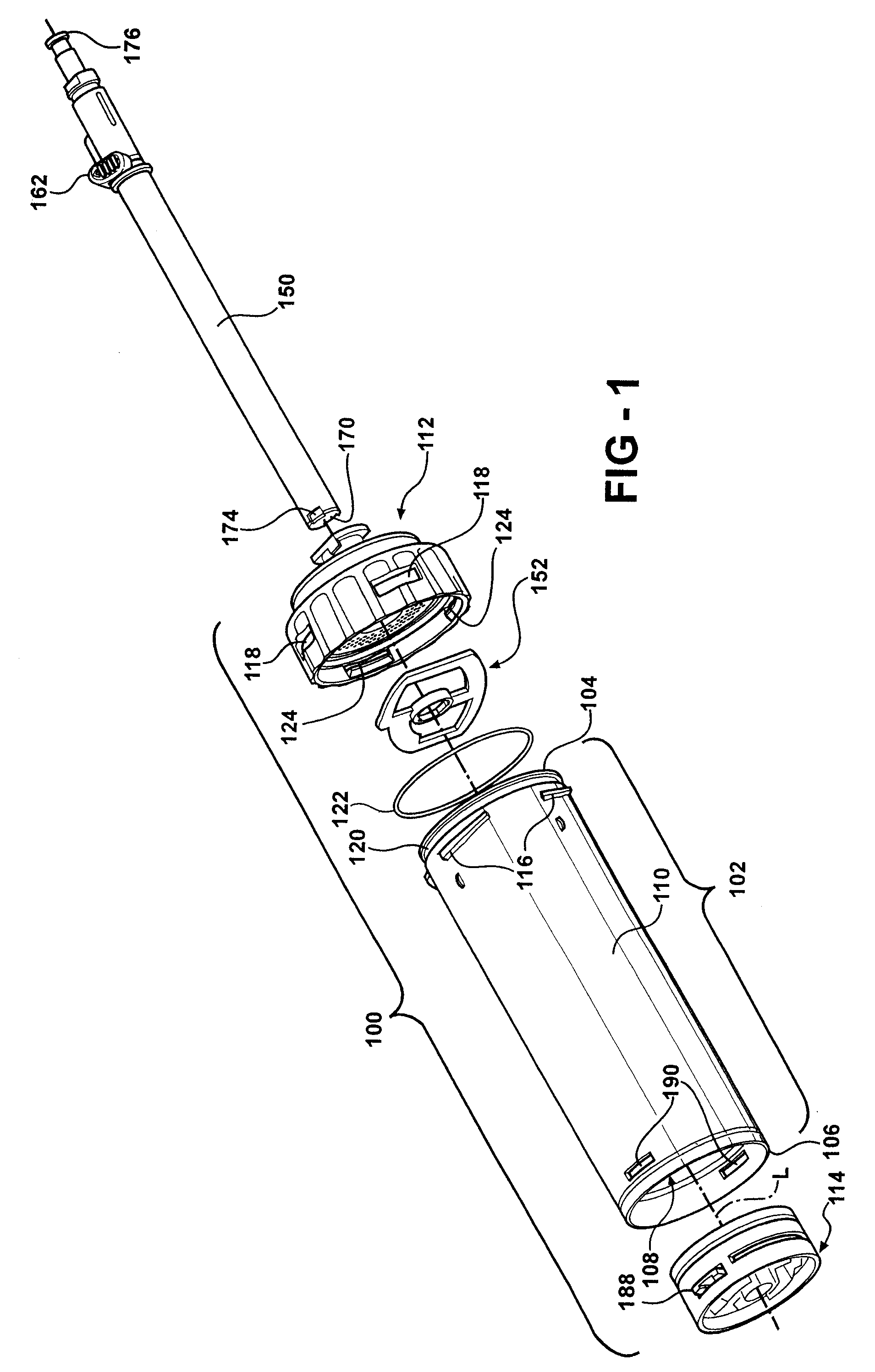
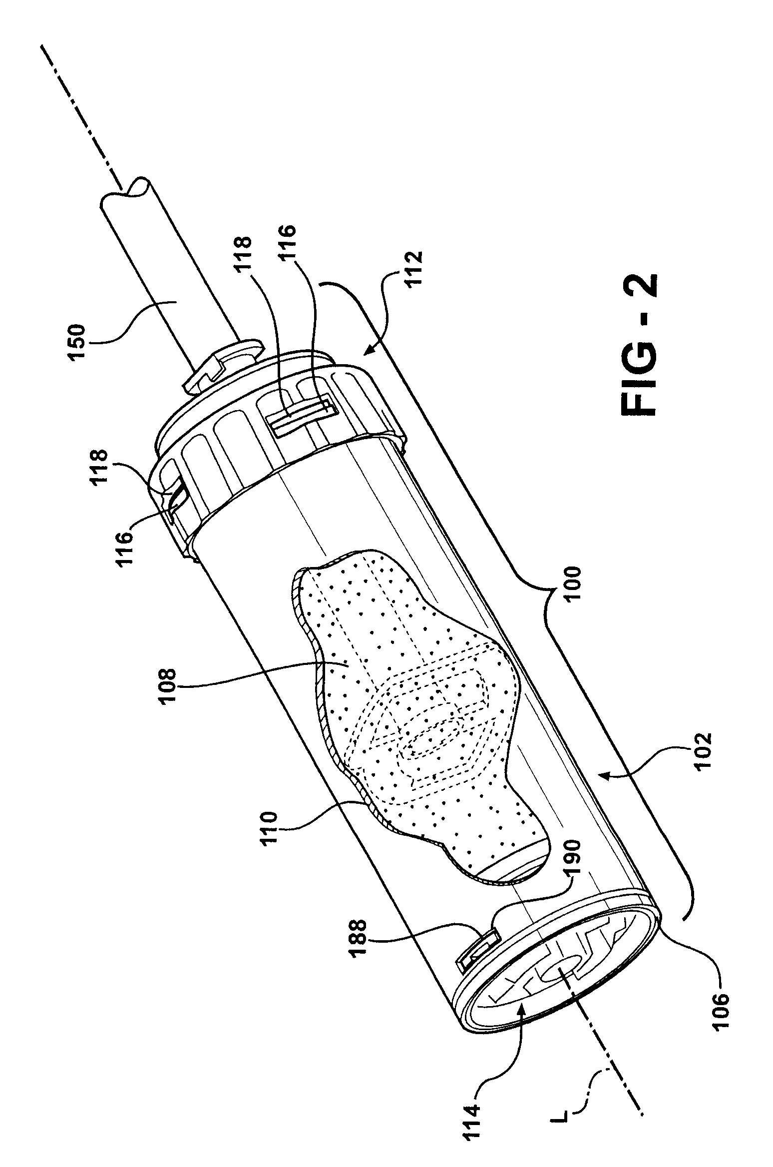
[0053]Referring to the Figures, wherein like numerals indicate like or corresponding parts throughout the several views, a bone cement mixing and delivery system is generally shown. The bone cement mixing and delivery system comprises a mixing cartridge 100 for receiving liquid monomer and powdered copolymer components of bone cement to be mixed, a mixing device (mixing shaft 150 and blade 152) for mixing the components, and a delivery device, e.g., a delivery gun 500, for discharging the bone cement from the mixing cartridge 100 into an anatomical site (not shown). An exemplary use for the bone cement is to secure a prosthetic device used to replace a joint structure such as in a total hip arthroplasty (THA) procedure.

[0054]Referring to FIGS. 1 and 2, the bone cement mixing system comprises the mixing cartridge 100 in combination with the mixing shaft 150 and blade 152 used to mix the components of the bone cement in the mixing cartridge 100. The mixing cartridge 100 includes a cyl...


PUM

PropertyMeasurementUnit
angleaaaaaaaaaa
acute angleaaaaaaaaaa

Abstract

A bone cement mixing and delivery system is provided. The system includes a mixing cartridge for receiving liquid and powder components of bone cement, a mixing device for mixing the components, and a delivery gun for discharging the bone cement from the mixing cartridge. The mixing cartridge comprises a cylinder having proximal and distal ends with a cylinder wall extending between the ends. A piston is locked at the distal end by a locking member that includes a pair of locking tabs protruding into slots in the cylinder wall. With the piston in the locked position, the mixing device, e.g., a mixing shaft and blade, mixes the components. After mixing, the cartridge is placed in the delivery gun and release buttons on the locking member are engaged by a release mechanism on the delivery gun to release the piston from the locked position.

Description

RELATED APPLICATIONS[0001]This application is a divisional of application Ser. No. 10 / 843,813, filed May 12, 2004, and claims the benefit of U.S. Provisional Patent Application Ser. No. 60 / 469,651, filed May 12, 2003 and U.S. Provisional Patent Application Ser. No. 60 / 520,877, filed Nov. 18, 2003. The advantages and disclosures of each of the aforementioned applications are hereby incorporated by reference.FIELD OF THE INVENTION[0002]The present invention generally relates to a bone cement mixing and delivery system. More specifically, the present invention relates to a mixing cartridge for receiving liquid and powder components of bone cement to be mixed, a mixing device for mixing the components, and a delivery gun for discharging the bone cement from the mixing cartridge into an anatomical site of a patient.BACKGROUND OF THE INVENTION[0003]Bone cement mixing and delivery systems are well known for mixing liquid and powder components of bone cement and delivering the prepared bone...

Claims


Application Information

Patent Timeline
Patent Type & Authority Patents(United States)
IPC IPC(8): A61M5/00B01F15/02G01F11/32A61CA61F2/00B01F33/40B29B7/16
CPCA61B17/8822B01F13/002B01F15/027B01F15/0279B01F11/0054A61B2017/8838A61F2002/30426A61F2002/4685A61F2002/469A61F2220/0025B01F2215/0029B01F15/00487B01F15/00506B01F2015/00584A61B17/8827B01F31/40B01F33/5011B01F35/32005B01F35/3202B01F35/3211B01F35/562B01F35/752B01F35/754251B01F2101/20
Inventor HENNIGES, BRUCE D.COFFEEN, JARED P.
Owner STRYKER CORP
Why Eureka
Try Eureka