Actuator

a technology of actuators and actuators, which is applied in the direction of motors/generators/converter stoppers, instruments, dynamo-electric converter control, etc., can solve the problems of insufficient redundancy to use as actuators for driving the control surface of aircraft, and the inability to drive the piston, so as to reduce the vibration of the member to be driven

Active Publication Date: 2008-07-08
NABLESCO CORP
View PDF2 Cites 22 Cited by
  • Summary
  • Abstract
  • Description
  • Claims
  • Application Information

AI Technical Summary

Benefits of technology

[0010]With this configuration, it is possible to drive the movable rod using either electric power or fluid pressure. In addition, it is possible to provide an actuator having redundancy.
[0012]With this configuration, the output rotation of the electric motor can be reliably transmitted to the screw shaft through the gear mechanism. Further, a degree of freedom for layout of the electric motor can be increased, and a compact actuator can be provided as a whole.
[0014]With this configuration, the movable rod can be reliably driven using fluid pressure by a simple operation of switching of the switch valve.
[0016]With this configuration, when the movable rod is driven by the electric motor, the mode selector valve is switched to the second position, such that both ports communicate with each other. Therefore, locking of the piston by fluid pressure can be prevented, and thus the movably rod can be smoothly driven using electric power.
[0018]With this configuration, when the working fluid pressure is lost, the second switch value is automatically switched to the second position by the bias spring, such that both ports communicate with each other. Therefore, locking of the piston by fluid pressure can be prevented, and thus the piston can keep a state suitable for driving of the movable rod by electric power.
[0020]With this configuration, excessive vibration of a member to be driven can be reduced by a fluid pressure damping effect.

Problems solved by technology

However, according to the configuration of FIG. 1 of JP-A-11-272332, when an oil pressure is lost, it may be impossible to drive the piston, and thus redundancy enough to use as an actuator for driving a control surface of an aircraft may be not secured.

Method used


Image

  • Actuator
  • Actuator
  • Actuator

Examples


Embodiment Construction

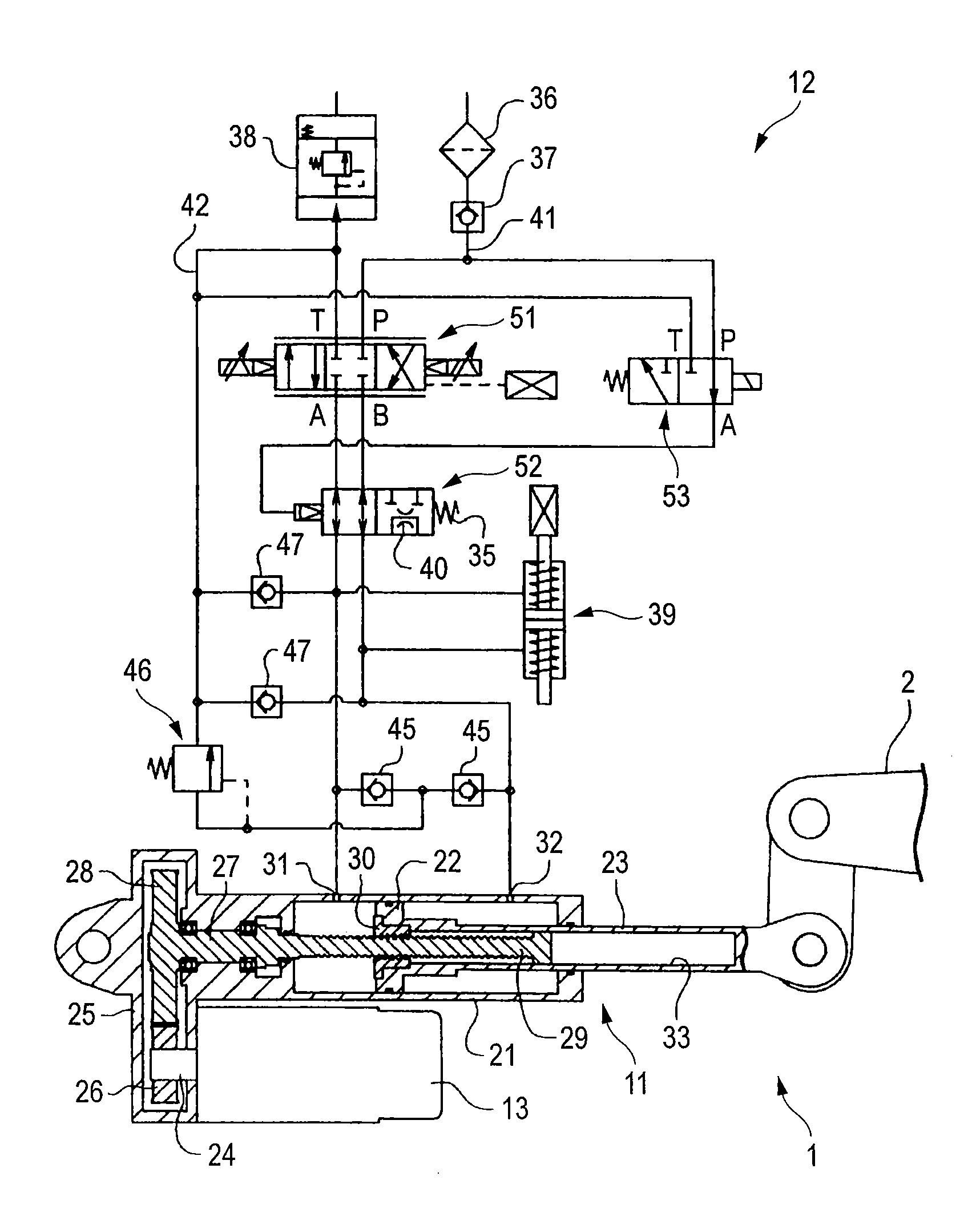
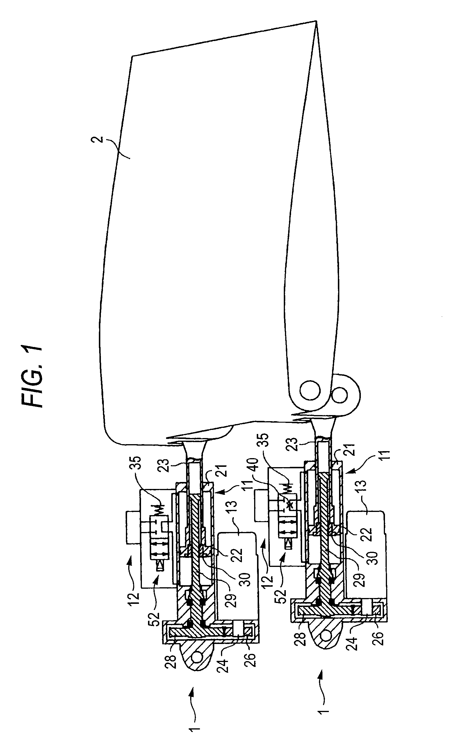
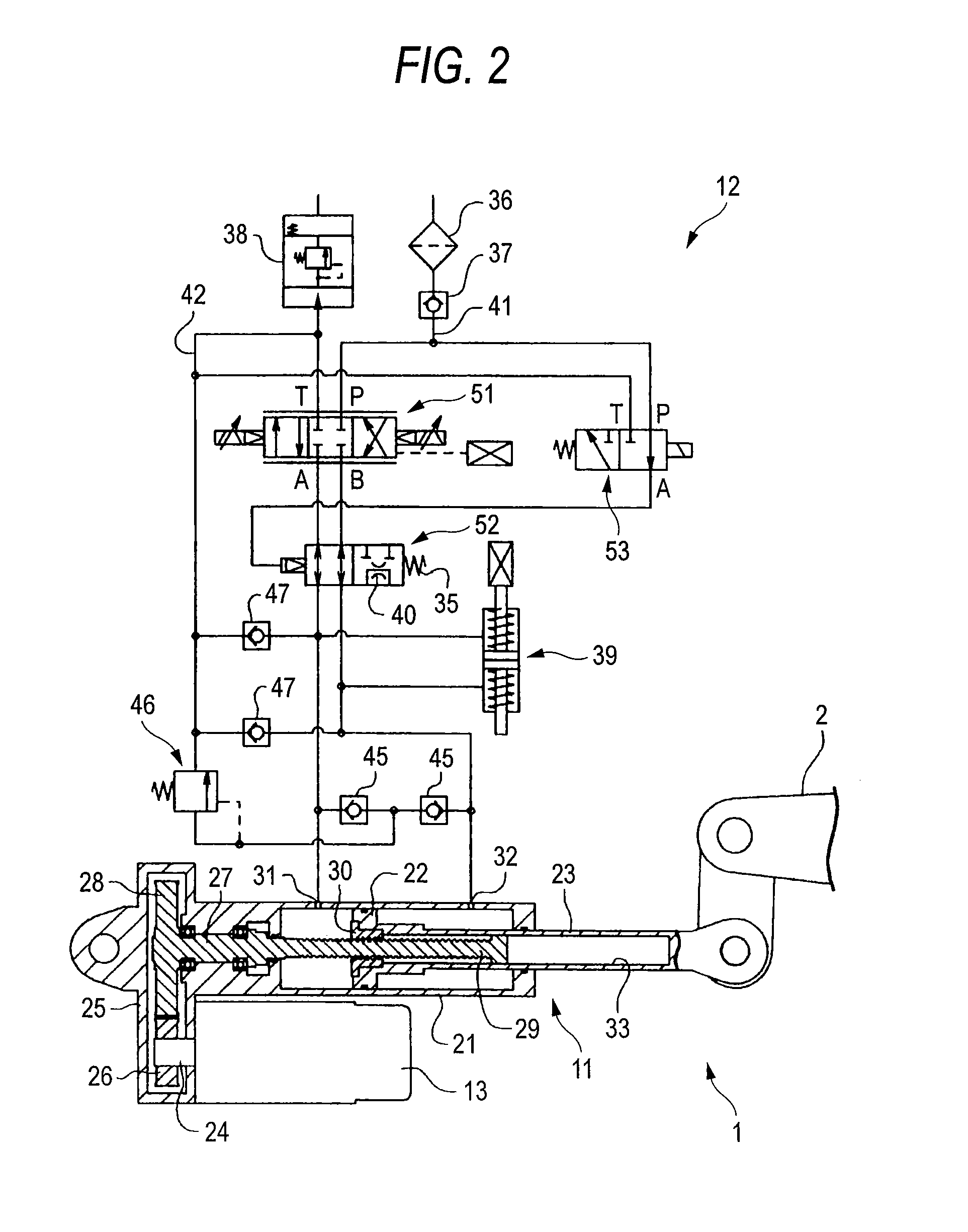
[0031]Next, an embodiment of the invention will be described. FIG. 1 is a schematic perspective view showing the configuration for driving a control surface by an actuator according to an embodiment of the invention. FIG. 2 is a cross-sectional view showing the configuration of an individual actuator and a circuit diagram of an oil pressure circuit.

[0032]Actuators 1 shown in FIG. 1 are to drive a control surface 2 provided in an aircraft. Two actuators 1 are provided in a pair. FIG. 2 shows the configuration of an individual actuator 1. The actuator 1 primarily includes a cylinder mechanism 11, an oil pressure circuit 12 that drives the cylinder mechanism 11, and an electric motor 13 that drives the cylinder mechanism 11.

[0033]The cylinder mechanism 11 includes a cylinder 21, and a piston 22 that is disposed in the cylinder 21. The piston 22 is fitted into the cylinder 21 oil-tight, and reciprocates in an axial direction of the cylinder 21. The piston 22 is provided to divide the in...


PUM


Abstract

An actuator includes a cylinder, a piston that is disposed in the cylinder and moves by supply and exhaust of working oil to and from the cylinder, a movable rod that is connected to the piston, a screw shaft, at least a part of which is inserted into the movable rod, a nut that is threaded to the screw shaft and moves integrally with the piston, and an electric motor that rotates the screw shaft forward or backward.

Description

BACKGROUND OF THE INVENTION[0001]1. Field of the Invention[0002]The present invention relates to an actuator that can drive a movable rod using fluid pressure or electric power.[0003]2. Related Art[0004]Japanese Patent Publication No. JP-A-11-272332 discloses a positioning cylinder device. The cylinder device has a ball screw and a nut that are disposed in a piston rod of a cylinder. In this configuration, a linear motion of the piston is converted into a rotation motion through the ball screw, and the rotation motion is converted into a positional signal by an angle sensor (for example, an encoder). Then, a switch valve is fed back on the basis of the signal, and the piston is positioned.[0005]In JP-A-11-272332, with this configuration, a position of a stroke end of the piston rod can be changed. Further, in JP-A-11-272332, there is disclosed a case where the piston rod is driven by a motor as well as an electro-hydraulic servo valve.[0006]However, according to the configuration of...

Claims


Application Information

Patent Timeline
Patent Type & Authority Patents(United States)
IPC IPC(8): H02P1/00
CPCB64C13/42F15B20/00F15B15/088F15B2015/1495B64C13/341B64C13/505
Inventor HIRAI, MASANORI
Owner NABLESCO CORP
Why Eureka
Try Eureka