Image display apparatus and head mount display

a display apparatus and display head technology, applied in the field of image display apparatus and head mount display, can solve the problems of reducing both the illumination efficiency and the quality of the image, unable to lighten, and difficult to integrate pixels at higher density, so as to reduce the thickness or overall size of the apparatus

Active Publication Date: 2008-07-29
KONICA MINOLTA INC
View PDF9 Cites 46 Cited by
  • Summary
  • Abstract
  • Description
  • Claims
  • Application Information

AI Technical Summary

Benefits of technology

[0025]The prevent invention has been developed in order to solve the foregoing problems, and an object thereof is to provide an image display apparatus arranged in which an optical path extending from a light source to a reflective type display device is bent at an appropriate position thus to decrease the thickness or overall size of the apparatus and a head-mount display equipped with the image display apparatus.
[0026]It is another object of the present invention to provide an image display apparatus arranged in which the diffraction wavelength range of the R, G, and B colors of light in a hologram optical element is properly determined in combination with the wavelength range of the R, G, and B colors of the light emitted from a light source thus to widen the color reproduction area and thus improve the quality of an image developed on a display device which is driven in a time-division mode and a head-mount display equipped with the image display apparatus.
[0030]According to the above arrangement, the light source can be located adjacent to the optical path which extends from the reflective type display device to the eyepiece optical system with no need of increasing the optical power of the illumination optical system while its optical path remains at a distance required for illuminating the reflective type display device. In addition, since the light source and the optical-path bending member are located opposite to each other about the optical path which extends from the reflective type display device to the eyepiece optical system, a three-piece group of the light source, the optical-path bending member, and the reflective type display device are allocated adjacent to the eyepiece optical system in compactness. As the result, the apparatus can easily be minimized in the thickness or overall size.
[0032]According to the above arrangement, each of the pixels in the display device can be driven in a time-division mode in response to each of the three primary (R, G, and B) colors of the light emitted in a time-division sequence from the light source. The image light in RGB is released in a sequence from the display device, diffracted by the hologram optical element in the eyepiece optical system, and directed to the pupil of the viewer. This allows the viewer to view the color image.
[0033]Since the relationship between the wavelength range Δλ1 at half of the diffraction efficiency of the light in the hologram optical element and the wavelength range Δλ2 at half of the intensity of the light emitted from the light source is expressed by Δλ1<Δλ2 at each of the three primary colors of the light, a desired component at the wavelengths of the R, G, and B colors of the light emitted from the light source can favorably be diffracted in the hologram optical element before received by the pupil of the viewer. Accordingly, the image to be viewed, which has been produced by the display device actuated in a time-division mode, can be improved in the purity of each of the R, G, and B colors and its color reproduction area can be widen more than the color reproduction area determined directly from the light emitted from the light source.

Problems solved by technology

This limits the semiconductor process in the production thus making the integration of pixels at higher density difficult.
When the integration of pixels is increased, the proportion of the pixel area to the screen of the display panel (so called the aperture) becomes smaller thus declining both the illumination efficiency and the quality of the image.
However, the conventional image display apparatus includes the PBS 103 which is considerably heavy and will thus remain not lightened.
Accordingly, the apparatus will be limited in the downsizing and configured in an unfavorable layout possibly with its light source 201 projecting towards the viewer.
As the result, the apparatus will be increased in the height thus interrupting the downsizing.
As the result, the downsizing of the apparatus will be interrupted.

Method used


Image

  • Image display apparatus and head mount display
  • Image display apparatus and head mount display
  • Image display apparatus and head mount display

Examples


embodiment 1

[0061]Embodiment 1 of the present invention will be described referring to the relevant drawings.

1. Arrangement of HMD

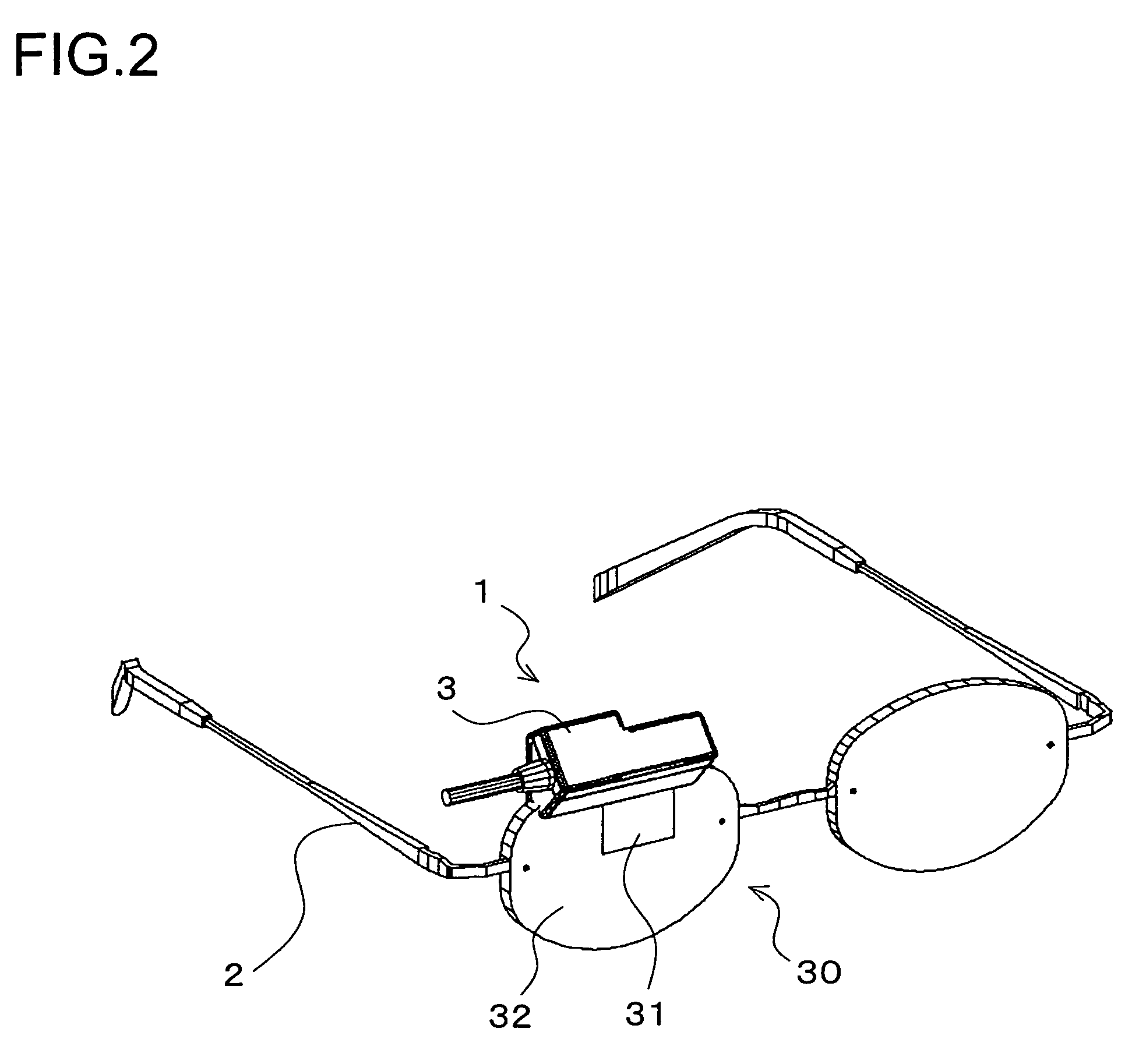
[0062]FIG. 2 is a perspective view schematically showing an arrangement of a head mount display (hereinafter referred to as an HMD) according to the present invention. The HMD includes an image display apparatus 1 and a supporting member 2 (supporting means) for supporting the image display apparatus 1 in front of eyes of a viewer.

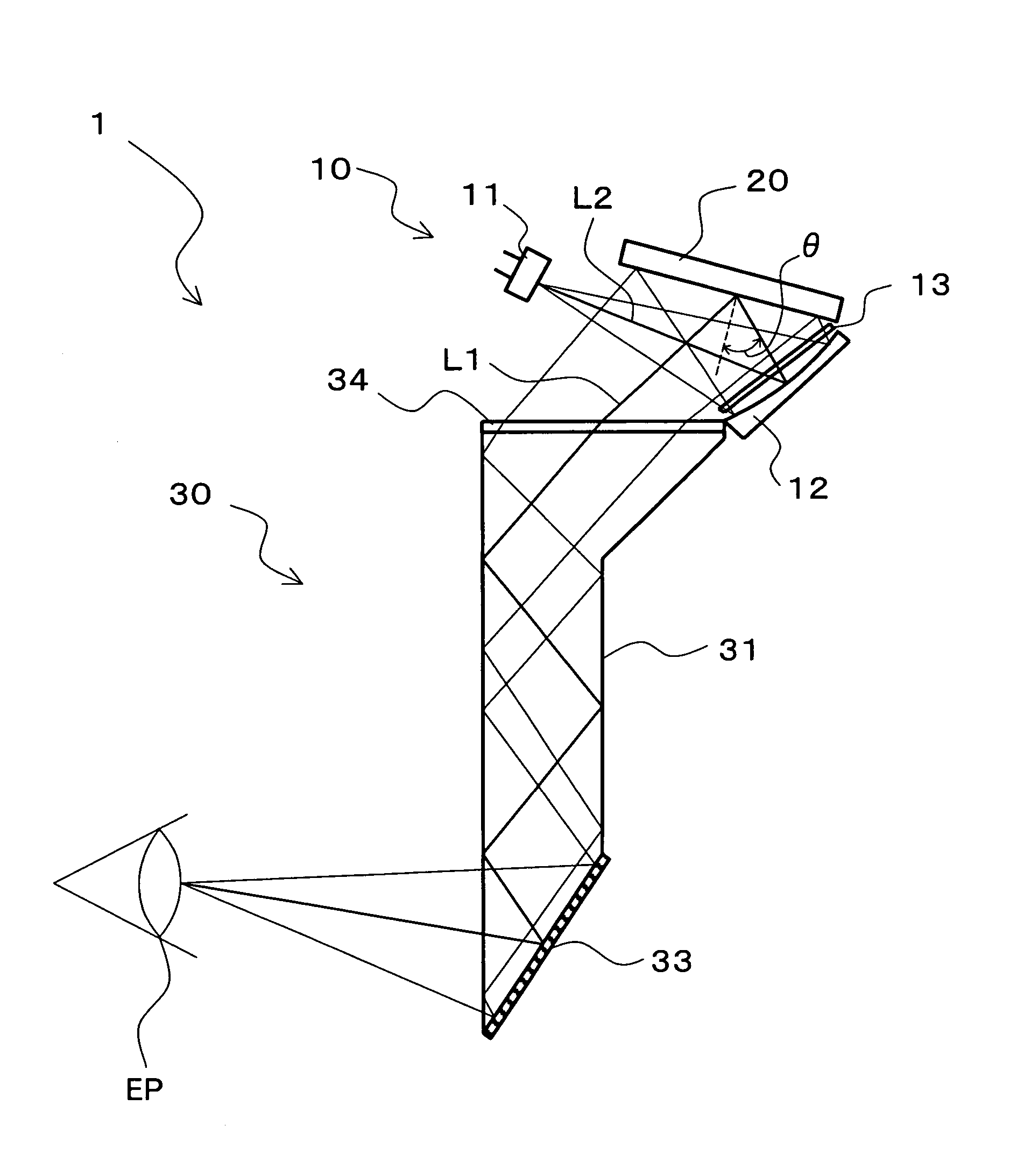
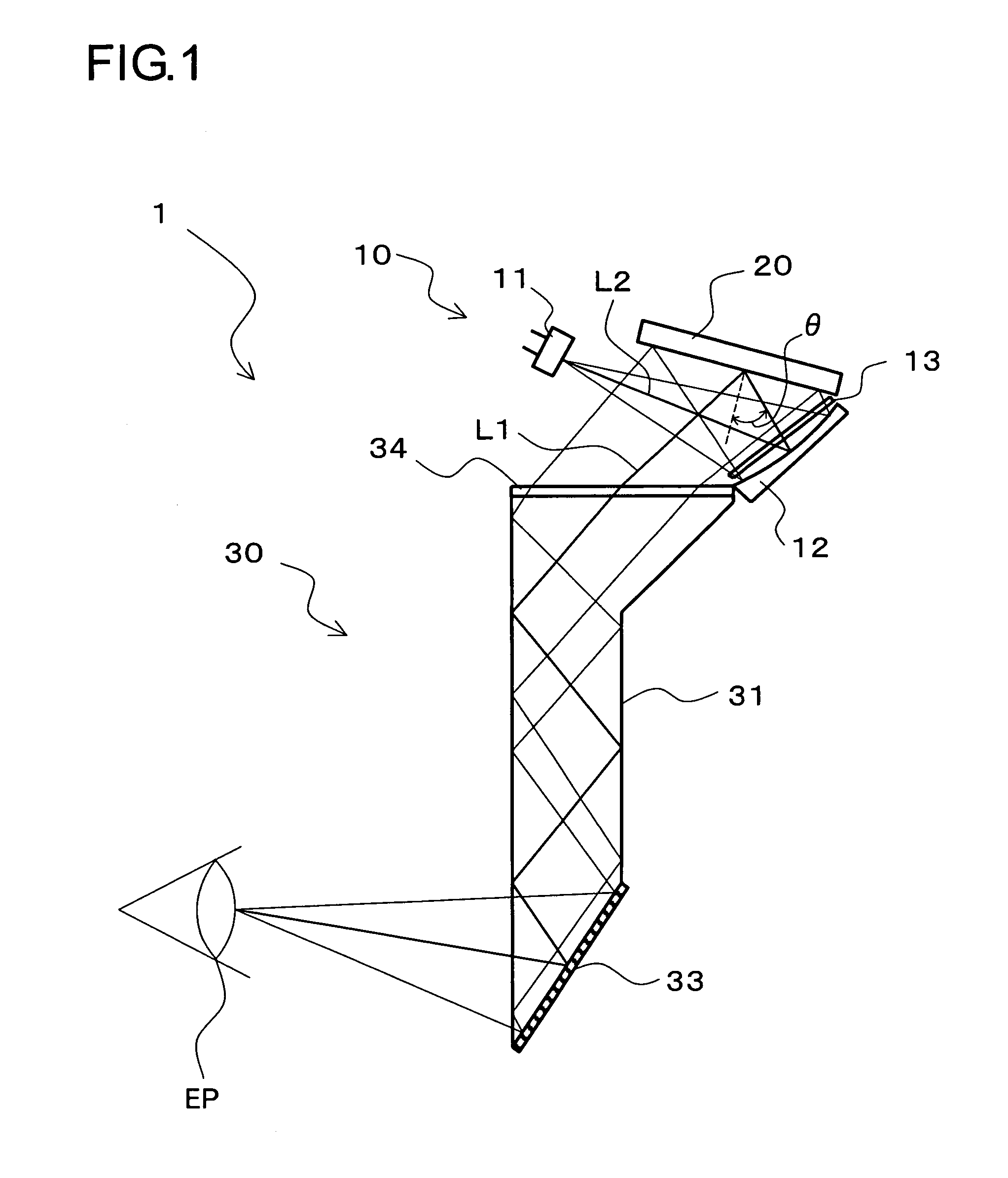
[0063]The image display apparatus 1 is arranged for allowing the viewer to view background or external scene in a see-through manner, and at the same time providing an image of interest to be viewed as a virtual image by the viewer. The image display apparatus 1 includes an illumination optical system 10 (See FIG. 1) and a display device 20 (see FIG. 1) both installed in a housing 3 and an eyepiece optical system 30 assembled together with the housing 3. The eyepiece optical system 30 is arranged of substantially one of spectacles (the righ...

embodiment 2

[0163]Another embodiment of the present invention will be described referring to the relevant drawings. For ease of the description, like elements are denoted by like numerals as those of Embodiment 1 and will be explained in no more detail.

[0164]FIG. 12 is a cross sectional view schematically showing an arrangement of an image display apparatus 1 of this embodiment. In this embodiment, the eyepiece optical system 30 includes a free-surface prism 35 which replaces the eyepiece prism 31 in Embodiment 1.

[0165]The free-surface prism 35 has a first surface 35a thereof provided as the incident surface for receiving an image light from the display device 20, a second surface 35b thereof provided at the viewer pupil EP side for acting as the full reflection / transmission surface, and a third surface 35c thereof provided as the reflecting surface to face the second surface 35b. The three surfaces are arranged of an aspherical shape at non-rotating symmetry. The first surface 35a is arcuately...

embodiment 3

[0171]A further embodiment of the present invention will be described referring to the relevant drawings. For ease of the description, like elements are denoted by like numerals as those of Embodiment 1 or 2 and will be explained in no more detail.

[0172]FIG. 13 is a cross sectional view schematically showing an arrangement of an image display apparatus 1 of this embodiment. In this embodiment, the illumination optical system 10 in Embodiment 1 further includes a diffuser plate 17.

[0173]The diffuser plate 17 is provided for diffusing the incident light received along the optical path bent by the concave mirror 12. When the B, G, and R emitters of the light source 11 are aligned along the long side of the display device 20, the diffuser plate 17 may be arranged in a one-way diffusion mode to diffuse the incident light along the direction of the long side. Alternatively, the diffuser plate 17 may has a surface thereof undulated or be implemented by a hologram optical element of volume ...


PUM


Abstract

The light directed from a light source to a concave mirror and the light directed from a display device to an eyepiece optical system are intersected by each other in a layout. This allows the light source, the concave mirror, and the display device to be arranged in compactness adjacent to the eyepiece optical system without increasing the optical power of an illumination optical system. As the result, the apparatus can easily be minimized in the thickness or the overall size. A hologram optical element is provided where the relationship between the wavelength range Δλ1 at half of the diffraction efficiency of each of the three primary colors of the light in the hologram optical element and the wavelength range Δλ2 at half of the intensity of each of the three primary colors of the light emitted from the light source is defined by Δλ1<Δλ2. Accordingly, a component at desired wavelengths of each of the R, G, and B colors of the light emitted from the light source can be diffracted by the action of the hologram optical element and then directed to the pupil of the viewer. This allows the image to be increased in the color reproduction area and improved in the quality regardless of the display device actuated in a time-division mode.

Description

[0001]This application is based on the Japanese Unexamined Applications No. 2005-156906 filed on May 30, 2005, No. 2005-235626 filed on Aug. 16, 2005, and No. 2006-037932 filed on Feb. 15, 2006, of which the disclosures are hereby incorporated by reference.BACKGROUND OF THE INVENTION[0002]1. Field of the Invention[0003]The present invention relates to an image display apparatus for projecting an image displayed on a display device (for example, a reflective display device) onto the eyes of a viewer as a virtual image, and to a head mounted display (hereinafter referred to as an HMD) equipped with the image display apparatus.[0004]2. Description of the Prior Art[0005]An apparatus is known as a so-called HMD which is mounted on the head of a viewer for projecting the image, which has been produced by a display device, as a virtual image onto the pupil of the viewer across an eyepiece optical system. The display device employed in the HMD is classified into a transmissive type illumina...

Claims


Application Information

Patent Timeline
Patent Type & Authority Patents(United States)
IPC IPC(8): G02B27/14G09G5/00
CPCG02B5/32G02B27/0103G02B27/0172G02B5/30G03H2001/2231G02B2027/0112G02B2027/0174G02B2027/0178
Inventor SHIMIZU, YOSHIETANIJIRI, YASUSHINODA, TETSUYA
Owner KONICA MINOLTA INC
Why Eureka
Try Eureka