Method and apparatus for AC coupling a signal while restoring DC levels

a technology of restoring dc levels and coupling signals, applied in the field of video decoders, can solve the problems of incorrect brightness values, drooping actual signal level being received,

Active Publication Date: 2008-09-09
CIRRUS LOGIC INC
View PDF9 Cites 3 Cited by
  • Summary
  • Abstract
  • Description
  • Claims
  • Application Information

AI Technical Summary

Benefits of technology

[0009]A proper DC bias level for the composite video signal is developed by monitoring the sync tip voltage. The actual voltage of the sync tip is measured a number of times to develop an average value. This average value is compared to the desired level. To make any necessary adjustments, a charge is provided to the incoming signal by a current source. When the measurement is again performed, if there is an offset from the desired level, the setting on the current source is changed so that effectively the amount of charge being provided by the current source settles into the desired level. By having the current source provide charge during each video line, the proper DC bias level is developed. This proper DC bias level results in proper brightness levels in the output video signals.

Problems solved by technology

The decoder not only has to handle composite signals, which means it must be able to determine the chroma and luma values, but it also must handle vertical blanking interval (VBI) data and handle VCR signals, which may be unstable signals.
In many cases, the actual signal level being received will droop over time due to various leakage currents.
If this DC bias level is not correct, all brightness values will be incorrect.

Method used


Image

  • Method and apparatus for AC coupling a signal while restoring DC levels
  • Method and apparatus for AC coupling a signal while restoring DC levels
  • Method and apparatus for AC coupling a signal while restoring DC levels

Examples


Embodiment Construction

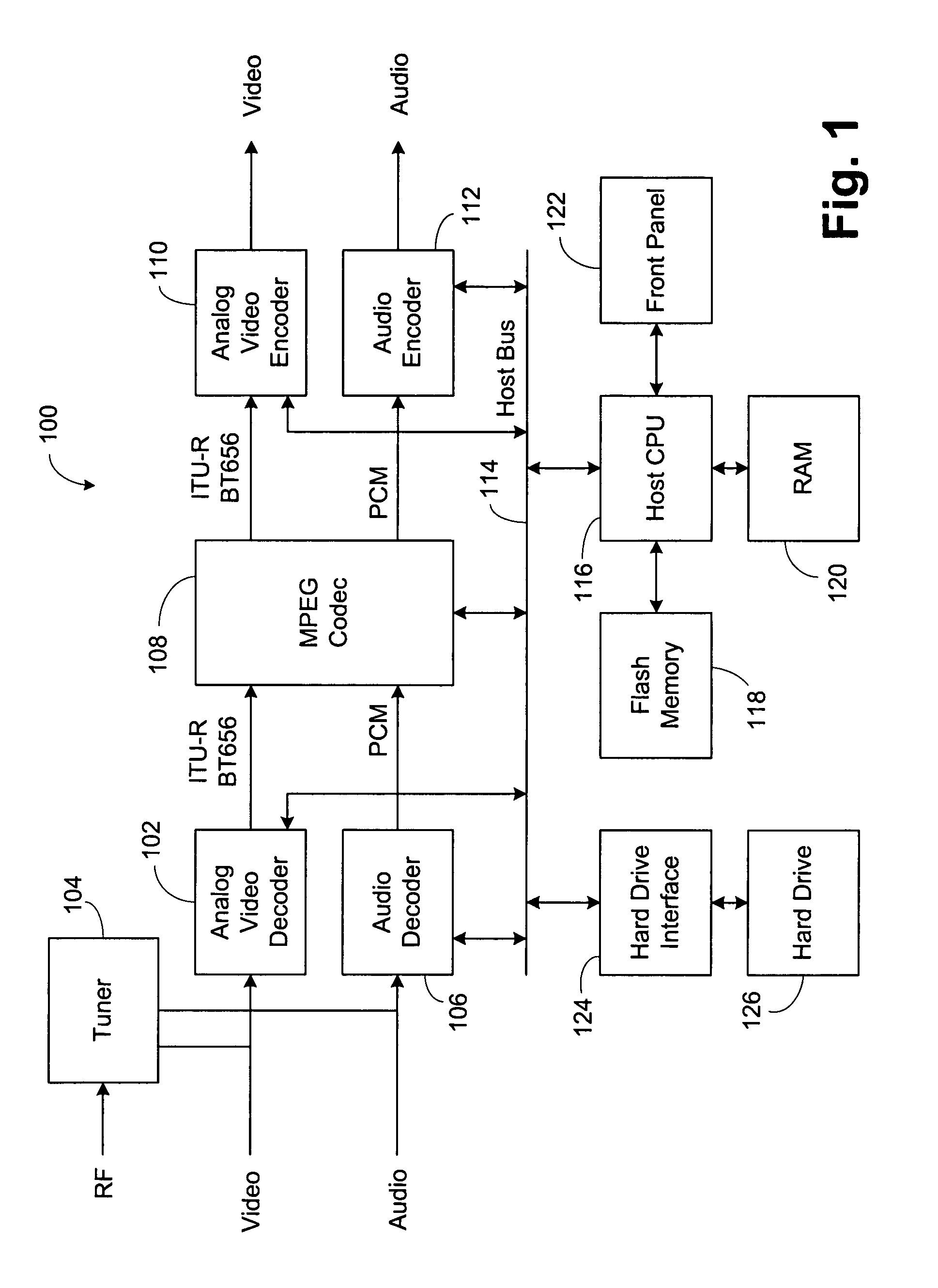
[0017]Referring now to FIG. 1, an exemplary personal video recorder (PVR) 100 is shown. PVR 100 is an exemplary use of analog video decoder 102, and it is understood that the analog video decoder 102 can be used in multiple applications including digital televisions, LCD TVs, DVD recorders, video capture situations, and the like. A radio frequency or broadcast signal is provided to a tuner 104. The tuner 104 provides both video and audio outputs. The video output from the tuner 104 or a video signal from an external connection is provided to analog video decoder 102. The audio signal from the tuner 104 or an external audio signal is provided to an audio decoder 106. The output of the analog video decoder 102 is preferably an ITU-R (International Telecommunication Union-Radio-Communication) BT (Broadcasting Service-television) 656 format digital signal, which is either an eight or ten bit signal. This output of the video decoder 102 is provided to an MPEG (Moving Pictures Expert Grou...


PUM


Abstract

A system in which drooping of the video levels due to leakage currents and proper DC bias level is addressed by providing a charge into the video signal to offset the leakage currents and to provide DC bias. To determine the leakage current level, measurements are made measuring the voltages of the syncs and the blanking intervals. To determine the DC bias, a measurement is made of the sync. Over a series of video lines these measurements are averaged. If the average is below the desired level, a charge is provided via a current source to the incoming signal. By having the current source provide charge during each video line, droop is reduced and the proper DC bias is provided.

Description

CROSS-REFERENCE TO RELATED APPLICATIONS[0001]This case is related to U.S. patent application Ser. No. 11 / 015,756 entitled, “Title: Method and Apparatus to Interface Video Signals to a Decoder to Compensate for Droop,” by Daniel Gudmundson, Shyam Somayajula, Ahsan Chowdhury, James Antone and Rahul Singh, filed concurrently herewith, which is hereby incorporated by reference.BACKGROUND OF THE INVENTION[0002]1. Field of the Inventions[0003]The inventions generally relates to video decoders, and more specifically to input video signal shaping, and even more specifically to providing constant video signal levels.[0004]2. Description of Related Art[0005]There is a large surge in the use of digital video devices today. Examples include: digital televisions, LCD (Liquid Crystal Display) TVs and monitors, DVD (Digital Versatile Disc) recorders, personal video recorders, PC (Personal Computers) video cards, video capture and streaming applications, and video conferencing. In many cases, these...

Claims


Application Information

Patent Timeline
Patent Type & Authority Patents(United States)
IPC IPC(8): H04N7/18
CPCH04N5/18H04N5/165
Inventor GUDMUNDSON, DANIELCHOWDURY, AHSAN HABIBANTONE, JAMES A.SINGH, RAHUL
Owner CIRRUS LOGIC INC
Why Eureka
Try Eureka