
Modifying duty cycles of PWM drive signals to compensate for LED driver mismatches in a multi-channel LED system

a multi-channel led and driver technology, applied in the field of multi-channel led (lightemitting diodes) systems, can solve the problems of limited ability of conventional led controllers to provide such current matching, and achieve the effect of improving aesthetic quality and viewability of the lcd display and uniform brightness

Active Publication Date: 2016-05-24
DIALOG SEMICONDUCTOR INC
View PDF9 Cites 4 Cited by
  • Summary
  • Abstract
  • Description
  • Claims
  • Application Information

AI Technical Summary

Benefits of technology

This approach effectively compensates for driver mismatches, achieving uniform average current and brightness levels across LED strings, thereby improving aesthetic quality and viewability in LCD displays.

Problems solved by technology

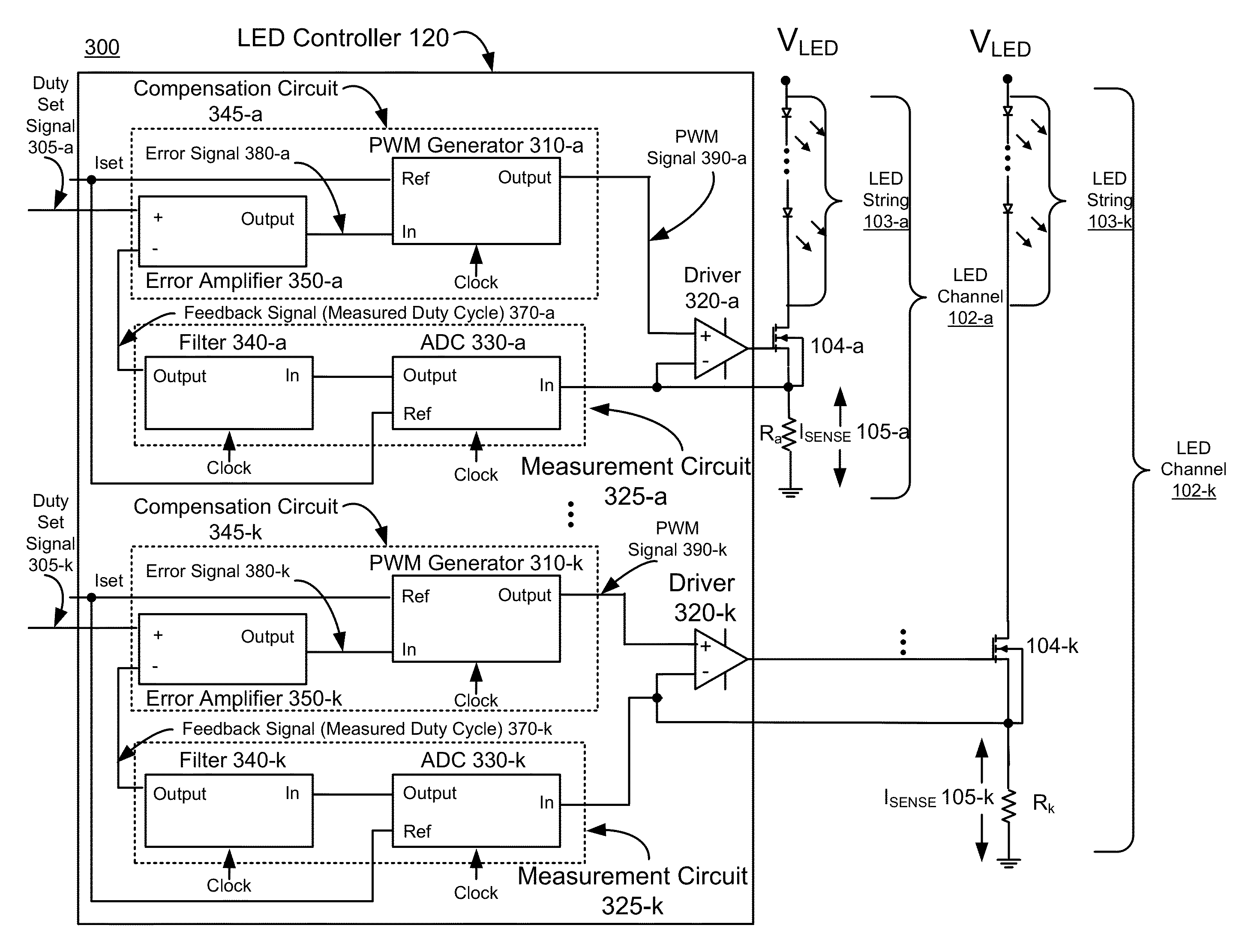
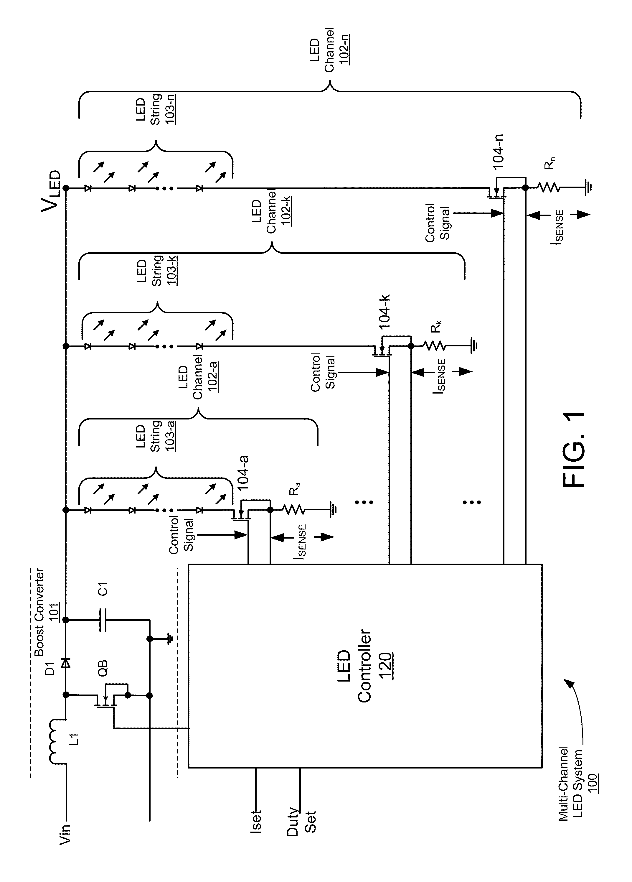
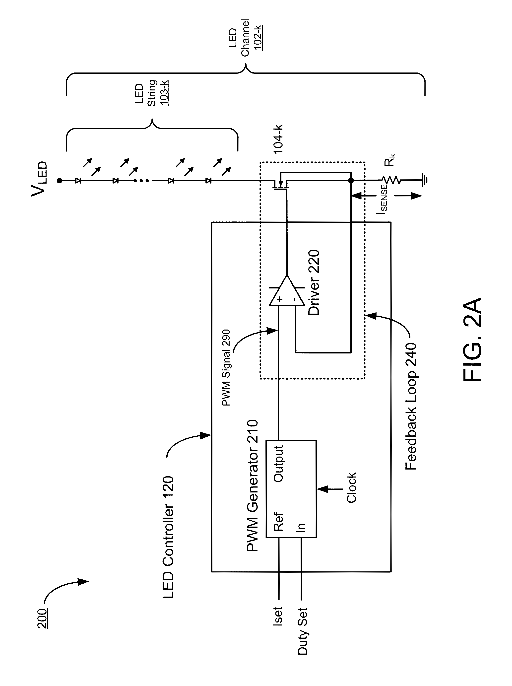
Conventional LED controllers are limited in their ability to provide such current matching owing to mismatches between drivers, within the controllers, that provide control signals to each of the one or more LED strings.

Method used


Image

  • Modifying duty cycles of PWM drive signals to compensate for LED driver mismatches in a multi-channel LED system
  • Modifying duty cycles of PWM drive signals to compensate for LED driver mismatches in a multi-channel LED system
  • Modifying duty cycles of PWM drive signals to compensate for LED driver mismatches in a multi-channel LED system

Examples


Embodiment Construction

[0023]The figures and the following description relate to preferred embodiments of the present disclosure by way of illustration only. It should be noted that from the following discussion, alternative embodiments of the structures and methods disclosed herein will be readily recognized as viable alternatives that may be employed without departing from the principles of the disclosure.

[0024]Reference will now be made in detail to several embodiments of the present invention(s), examples of which are illustrated in the accompanying figures. It is noted that wherever practicable similar or like reference numbers may be used in the figures and may indicate similar or like functionality. The figures depict embodiments of the present invention for purposes of illustration only. One skilled in the art will readily recognize from the following description that alternative embodiments of the structures and methods illustrated herein may be employed without departing from the principles of t...


PUM


Abstract

An LED (Light Emitting Diode) controller comprises a first LED driver to generate a first PWM (Pulse Width Modulation) drive signal to turn on or turn off, respectively, a first current through a first LED string. Additionally, the LED controller comprises a compensation circuit to generate the first PWM drive signal responsive to a first duty set signals. The first duty set signal is indicative of a first duty cycle set for the first PWM drive signal. The compensation circuit receives a first feedback signal indicative of the first current, generates a first error signal indicative of a difference between a first predetermined target value and the first feedback signal, and generates the first PWM drive signal to have the first duty cycle corresponding to the first duty set signal and further adjusted by the first error signal.

Description

CROSS-REFERENCE TO RELATED APPLICATION[0001]This application claims priority under 35 U.S.C. §119(e) from U.S. Provisional Patent Application No. 61 / 878,535, entitled “Feedback Configurations to Compensate for Driver Mismatches in a Multi-String LED System,” filed on Sep. 16, 2013, which is incorporated by reference herein in its entirety.BACKGROUND[0002]1. Technical Field[0003]The present disclosure relates generally to a multi-string LED (light-emitting diode) system and, more specifically, to feedback configurations for brightness matching in multi-string LED systems.[0004]2. Description of the Related Arts[0005]LEDs are used in a wide variety of electronics applications, for example, architectural lighting, automotive head and tail lights, backlights for liquid crystal display devices including personal computers and high definition TVs, flashlights, and the like.[0006]LEDs are current-driven devices, and thus regulating the current through the LEDs is an important control techn...

Claims


Application Information

Patent Timeline
Patent Type & Authority Patents(United States)
IPC IPC(8): H05B33/08H05B41/285H05B44/00
CPCH05B33/0887H05B33/0815H05B33/0827H05B33/0866H05B41/2851H05B45/24H05B45/46H05B45/3725H05B45/38
Inventor MALININ, ANDREY B.LIANG, ENZHUWANG, YUWEN
Owner DIALOG SEMICONDUCTOR INC
Learn More