Folding portable electronic equipment

a portable electronic equipment and folding technology, applied in the direction of rigid containers, packaging, transportation and packaging, etc., can solve the problems of accidental deformation of the appearance of the mobile phone, and achieve the effects of easy replacement, easy disassembly and assembly, and easy damag

Inactive Publication Date: 2008-10-28
SHARP KK
View PDF8 Cites 29 Cited by
  • Summary
  • Abstract
  • Description
  • Claims
  • Application Information

AI Technical Summary

Benefits of technology

[0014]In the above arrangement, the first fixing member is fixed to the first box body by means of the first fastening member with the first box body interposed between the first flat part and the first frame portion of the cover while the second fixing member is fixed to the second box body by means the second fastening member with the second box body interposed between the second flat part and the second frame portion of the cover. Accordingly, the cover is mounted firmly to the first and second box bodies, thereby being prevented from coming off accidentally. The first and second frame portions are fastened to the first and second box bodies, respectively, while being pushed by the first and second fixing members, respectively, preventing user's ear and the like from being in contact with the edge of the cover to lead to no invitation of user's unpleasant feeling. Further, the display section is exposed through the first cover window and the first fixing member window while the operation section is exposed through the second cover window and the second fixing member window, which means that the folding portable equipment with the cover can be used with no operability and viewability lowered. When the first and second fastening members are take off and the first and second fixing members are taken off, the cover can be replaced readily.
[0030]With the above arrangement, unique texture of the metal can be enjoyed. Further, with the fixing members having high rigidity, the receiver through hole and the mouthpiece through hole respectively formed in the first and second fixing members will not displaced, so that the fixing members will not cover the receiver through hole and the mouthpiece through hole.

Problems solved by technology

The users, who carry mobile phones, would often drop the mobile phones accidentally to deface the appearance thereof.

Method used


Image

  • Folding portable electronic equipment
  • Folding portable electronic equipment
  • Folding portable electronic equipment

Examples


Embodiment Construction

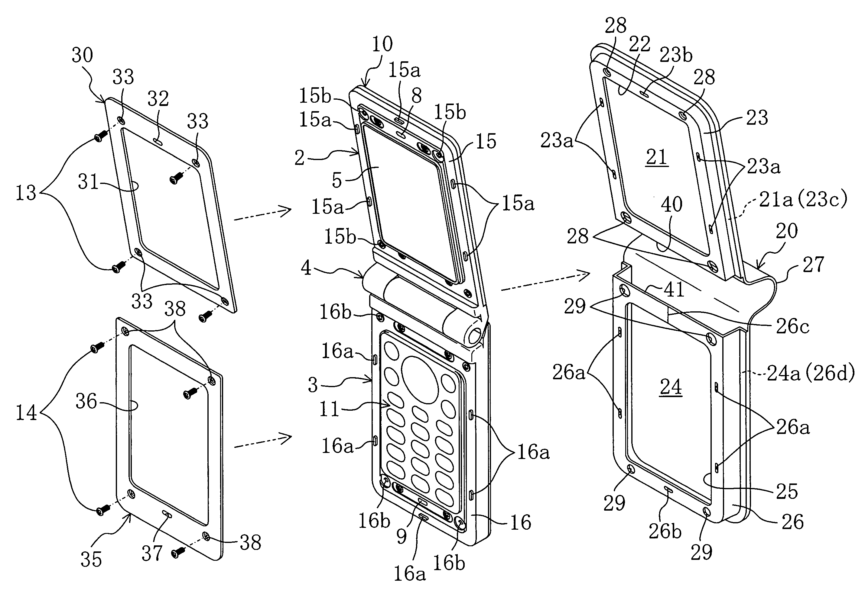
[0069]In the mobile phone 1 according to the present embodiment, the first fixing member 30 is fastened to the first box body 2 and the cover 20 by mean of the first fastening members 13 with the first box body 2 interposed between the first flat part 21 and the first frame portion 23 of the cover 20 while the second fixing member 35 is fastened to the second box body 3 and the cover 20 by means of the second fastening members 14 with the second boxy body 3 interposed between the second flat part 24 and the second frame portion 26 thereof. Accordingly, as well as the mobile phone 1 becomes tough to damage, it is hard to disassembled at use and is capable of being dressed up by easy replacement. Hence, the mobile phone 1 becomes good-looking and marketable.

Other Embodiments

[0070]The present invention may have any of the following variations in the above embodiment.

[0071]Namely, the slit 26c is formed at the upper side center, namely, the center of the side on the hinge 4 side of the ...


PUM


Abstract

A first box body is inserted between a first flat part and a first frame portion of a cover and is fastened to the cover by means of a first fastening member so that the first frame portion is interposed between the first box body and a plate-shaped first fixing member forming a first fixing member window for exposing a display section. A second box body is inserted between a second flat part and a second frame portion of the cover and is fastened to the cover by means of a second fastening member so that the second frame portion is interposed between the second box body and a plate-shaped second fixing member forming a second fixing member window for exposing an operation section.

Description

CROSS REFERENCE TO RELATED APPLICATIONS[0001]This Non-provisional application claims priority under 35 U.S.C. § 119(a) on Patent Application No. 2006-056775 filed in Japan on Mar. 2, 2006, the entire contents of which are hereby incorporated by reference.BACKGROUND OF THE INVENTION[0002]1. Field of the Invention[0003]The present invention relates to folding portable electronic equipment including a cover fitted thereto.[0004]2. Background Art[0005]Mobile phones are more and more widespread, and a great number of users of the mobile phones use them for sending / receiving e-mails and for making calls. The users, who carry mobile phones, would often drop the mobile phones accidentally to deface the appearance thereof.[0006]To tackling this problem, there have been proposed various mobile phones provided with a cover for preventing the phone main body from being damaged by dropping. The mobile phones with a cover are devised so as to be readily usable by detaching the cover or so as to b...

Claims


Application Information

Patent Timeline
Patent Type & Authority Patents(United States)
IPC IPC(8): H04M1/00H04M1/02H04M1/23
CPCH04M1/0216H04M1/0283H04B1/38
Inventor ODA, HIROFUMIIMAI, KIMIAKIHANDA, YOSHIHIKO
Owner SHARP KK
Why Eureka
Try Eureka