Turbine blade tip and shroud clearance control coating system

a technology of turbine blades and coating systems, which is applied in the direction of machines/engines, liquid fuel engines, superimposed coating processes, etc., can solve the problems of reducing the performance and performance retention of turbines, increasing the cost of engine operation and maintenance, and none of the systems try to minimize the friction between abrasive and abradable surfaces during engine operation

Active Publication Date: 2009-03-31
HONEYWELL INT INC
View PDF29 Cites 56 Cited by
  • Summary
  • Abstract
  • Description
  • Claims
  • Application Information

AI Technical Summary

Problems solved by technology

Increased blade tip clearance reduces turbine performance and performance retention during the service of the gas turbine engine, resulting in an increase in the expense of operation and maintenance of the engine.
However, while these rotary seal systems are an improvement over a blade and shroud with no abrasive or abradable coatings, respectively, none of the systems attempt to minimize the rubbing friction between the abrasive and abradable surfaces during engine operation.
Such friction may result in bending stresses that overload the blade to failure.

Method used


Image

  • Turbine blade tip and shroud clearance control coating system
  • Turbine blade tip and shroud clearance control coating system
  • Turbine blade tip and shroud clearance control coating system

Examples


Embodiment Construction

[0015]The following detailed description is of the best currently contemplated modes of carrying out the invention. The description is not to be taken in a limiting sense, but is made merely for the purpose of illustrating the general principles of the invention, since the scope of the invention is best defined by the appended claims.

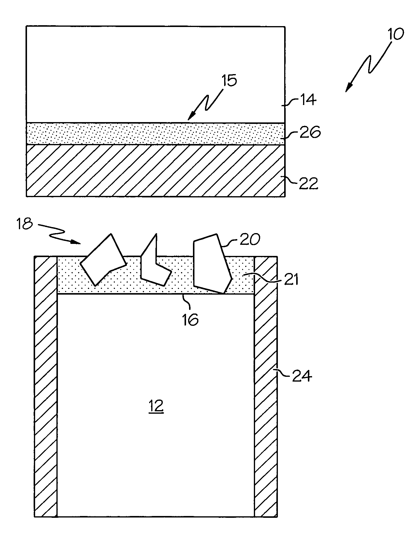
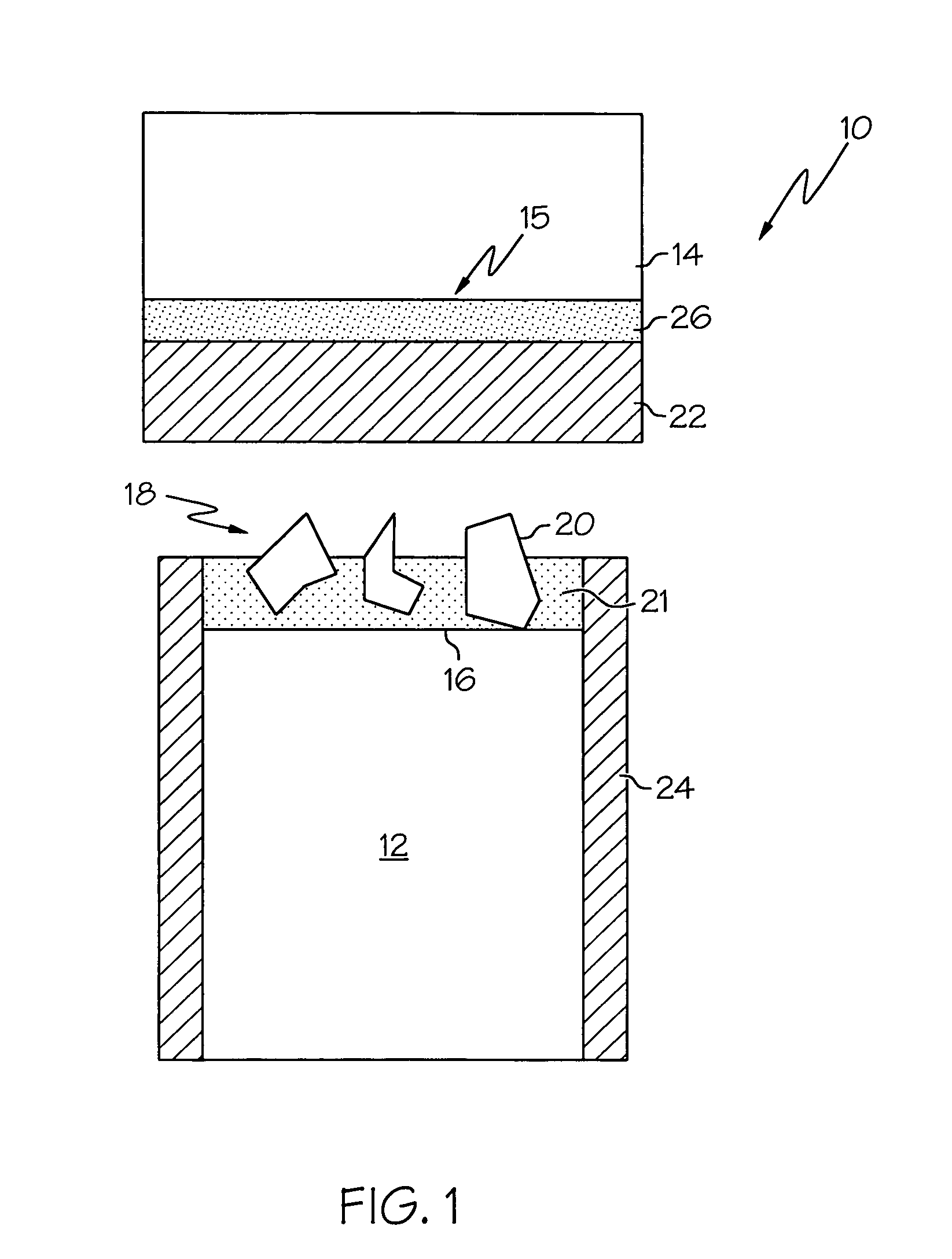
[0016]The present invention provides a turbine blade tip and shroud clearance control coating system which may comprise an abrasive coating on the blade tip and an abradable, nanolaminate thermal barrier coating on the inner surface of a shroud. The present invention may be used in gas turbine engines that require tight clearances between the blade tip and the inner surface of the shroud, particularly engines which operate in high heat environments and / or high wear applications.

[0017]The turbine blade tip and shroud clearance control coating system (referred to as the “coating system” herein) of the present invention may combine a blade tip having an ab...


PUM

PropertyMeasurementUnit
diameteraaaaaaaaaa
thicknessaaaaaaaaaa
melting temperatureaaaaaaaaaa

Abstract

A turbine blade tip and shroud clearance control coating system comprising an abrasive blade tip coating and an abradable shroud coating are provided. The abrasive layer may comprise abrasive particles of cubic zirconia, cubic hafnia or mixtures thereof, and the abradable layer may be a nanolaminate thermal barrier coating that is softer than the abrasive layer. The invention further provides an alternate coating system comprising an abradable blade tip coating and an abrasive shroud coating.

Description

CROSS REFERENCE TO RELATED APPLICATIONS[0001]This application claims the benefit of U.S. Provisional Application No. 60 / 648,781 filed Feb. 1, 2005, the disclosure of which is incorporated by reference herein.GOVERNMENT RIGHTS[0002]This invention was made with Government support under F33615-01-C-5233 awarded by the U.S. Air Force. The Government has certain rights in this invention.BACKGROUND OF THE INVENTION[0003]The present invention relates generally to coating systems for turbine blades and shrouds for gas turbine engines.[0004]Gas turbine engines typically include a variety of rotary seal systems to maintain differential working pressures that are critical to engine performance. One common type of seal system includes a rotating blade positioned in a rub relationship with the inner surface of a shroud. With the operation of a gas turbine engine, blade tip wear during rubs with the shroud along with blade tip oxidation can reduce blade tip height and increase the blade tip to sh...

Claims


Application Information

Patent Timeline
Patent Type & Authority Patents(United States)
IPC IPC(8): F01D5/20
CPCC23C26/02C23C30/00F01D5/20F01D11/122C23C28/321C23C28/3215C23C28/324C23C28/345C23C28/3455F05D2300/21F05D2300/2118
Inventor STRANGMAN, THOMAS E.RAYBOULD, DEREKCHIPKO, PAULMALAK, MALAK F.
Owner HONEYWELL INT INC
Why Eureka
Try Eureka