

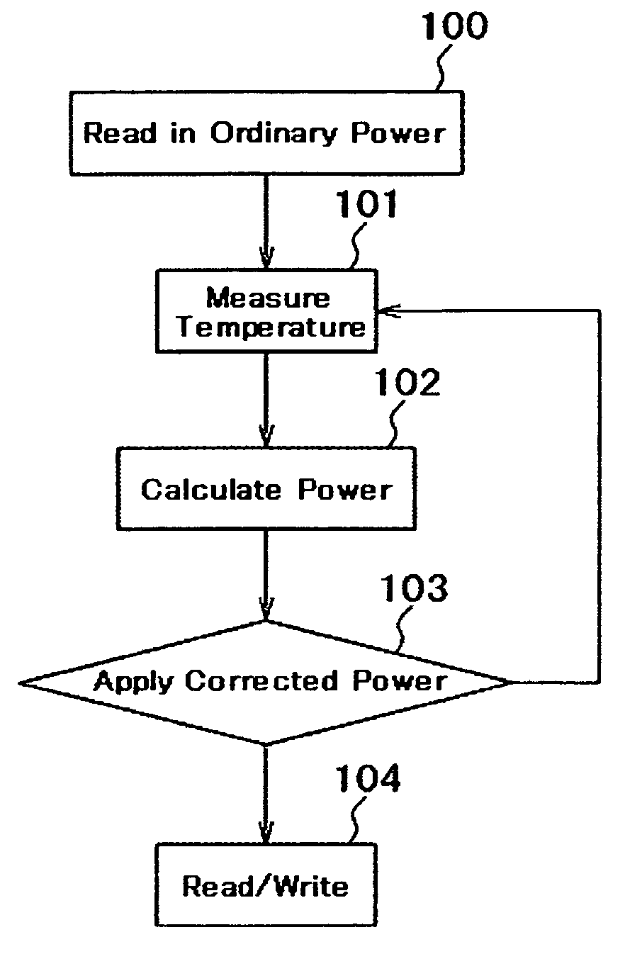
Magnetic disk drive with flying height control system
a control system and magnetic disk technology, applied in the field of magnetic disk drives, can solve the problems of frictional force on the protective film of the slider and the protective film of the disk, the slider contacts the magnetic disk and vibrates, and the read/write element is always close to the magnetic disk, so as to achieve the effect of high reliability, large storage capacity and constant distance between the read/write element and the magnetic disk
- Summary
- Abstract
- Description
- Claims
- Application Information
AI Technical Summary
Benefits of technology
Problems solved by technology
Method used
Image

Examples
Embodiment Construction
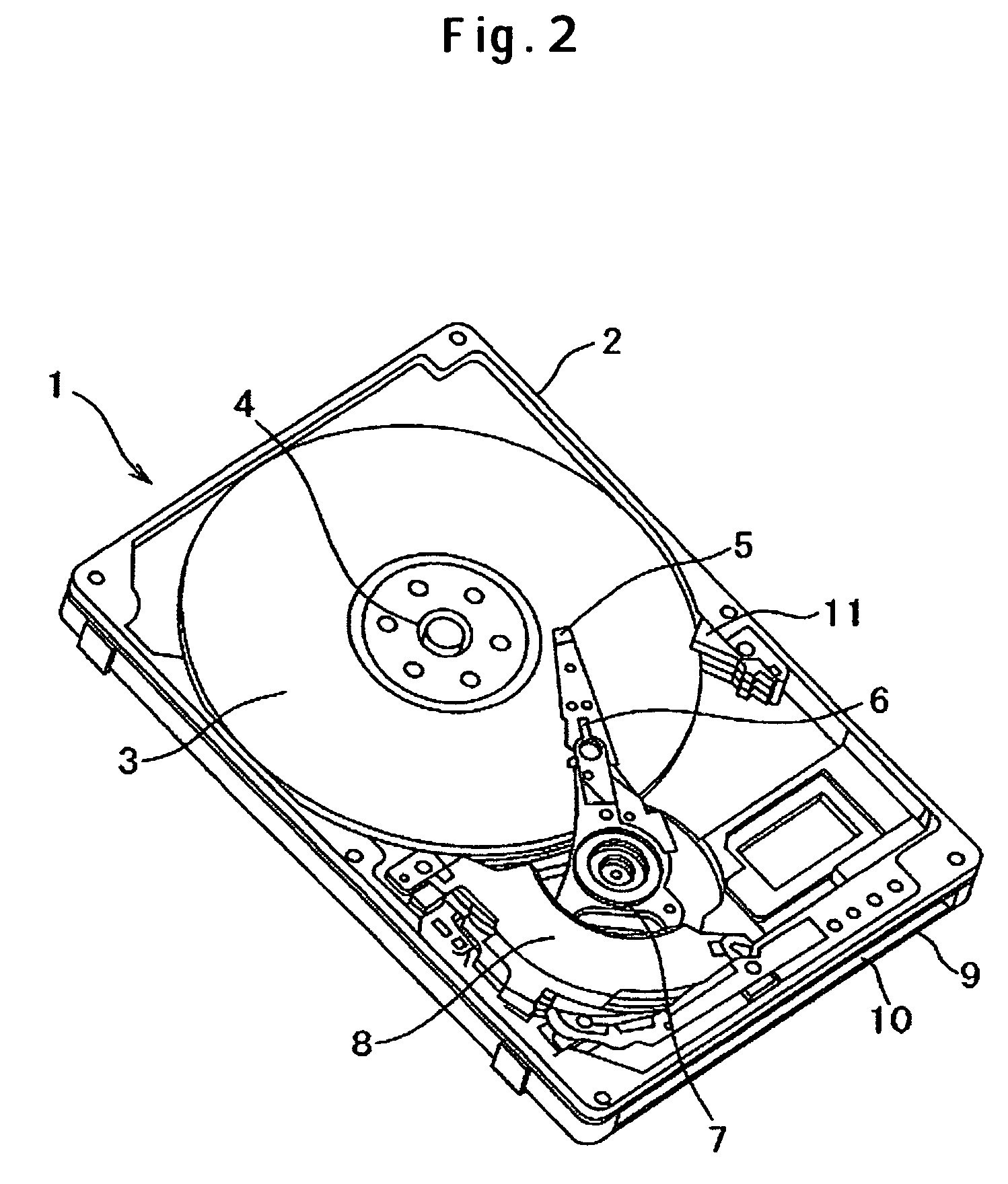
[0028]FIG. 2 schematically depicts the configuration of a magnetic disk drive according to an embodiment of the present invention. FIG. 3 is its block diagram including the control system. The magnetic disk drive 1 has a base 2 to form the enclosure, a cover (not shown in the figure) and a control circuit board 9 attached to the back side of the base 2. In FIG. 2, the cover is removed. Magnetic information is stored on a magnetic disk 3 which is rotated by a spindle motor 4 fixed on the base 2. Held and pressed toward the magnetic disk 3 by a suspension 6, a magnetic head slider 5 flies low above the magnetic disk 3 due to a flow of air generated by the rotating magnetic disk 3. When a seek operation is done to position the magnetic head slider 5 for read / write on the recording surface of the magnetic disk 3, the magnetic head slider 5 is moved in the radial direction of the magnetic disk 3 together with the suspension 6 by an actuator 7 which is driven by a voice coil motor (VCM) 8...
PUM
| Property | Measurement | Unit |
|---|---|---|
| temperature | aaaaa | aaaaa |
| temperature | aaaaa | aaaaa |
| flying height | aaaaa | aaaaa |
Abstract
Description
Claims
Application Information