Exhaust gas purifying system

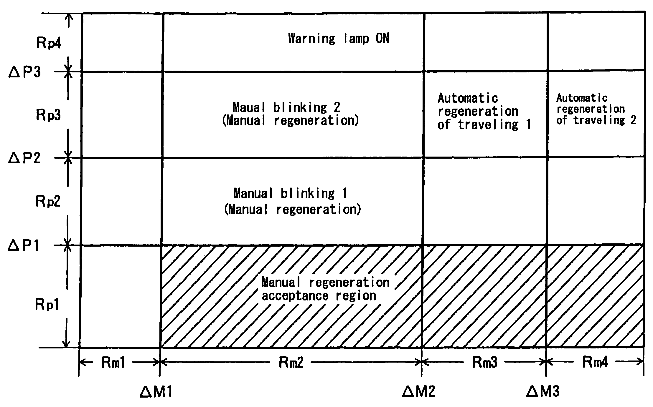
a technology of exhaust gas purification system and exhaust gas, which is applied in the direction of exhaust treatment electric control, electrical control, separation process, etc., can solve the problems of increasing exhaust pressure, increasing the frequency of blinking of lamps when manual regeneration is required, and preventing wear or seizing of machine sliding parts. , the effect of reducing the frequency of blinking of lamps

Active Publication Date: 2010-12-07
ISUZU MOTORS LTD
View PDF11 Cites 22 Cited by
  • Summary
  • Abstract
  • Description
  • Claims
  • Application Information

AI Technical Summary

Benefits of technology

[0023]The objective of this invention is, in an exhaust gas purifying system that prompts the driver through a warning from a blinking regeneration button to stop the vehicle and carry out manual regeneration by operation of the regeneration button when the detected collection amount is greater than a prescribed determining collection amount, to provide an exhaust gas purifying system that can carry out servicing manual regeneration even when there is no demand for manual regeneration, when conditions are such that manual regeneration may be carried out and when the driver can take the time, in the garage for example, and can reduce the number of times of warning from the blinking lamp of the regeneration button that prompts manual regeneration and by means of this can minimize its annoyance to the driver.
[0028]According to the exhaust gas purifying system of this invention, the traveling distance after forced regeneration is used in determining whether or not operation of the forced regenerating means for regenerating the DPF is possible. If vehicle has not traveled as far as the traveling distance where fuel commingled with the engine oil has evaporated and then oil dilution can be prevented in the forced regeneration when the vehicle is stopped, manual forced regeneration by the driver is not allowed, but after the vehicle has traveled the requisite traveling distance, manual operation by the driver of forced regeneration when the vehicle is stopped is allowed. In this manner it is possible to carry out the appropriate manual regeneration when convenient for the driver.
[0029]Consequently, while preventing wear or seizing of machine sliding parts in the engine caused by oil dilution at this forced regeneration time, manual regeneration can be carried out and the DPF can be force regenerated at a time favorable to the driver. As a result, the frequency of the blinking of the lamp when manual regeneration is required is minimized. Additionally, the prompting of manual regeneration when it is difficult for the driver to carry out manual regeneration is lessened. Accordingly, it is possible to alleviate the annoyance of the driver and improve convenience.

Problems solved by technology

Consequently, because the PM cannot be oxidized and the filter cannot be regenerated, accumulation of PM in the filter continues and filter clogging is promoted.
Accordingly, this produces the problem of increased exhaust pressure due to the clogging in this filter.
However, the following problem occurs when carrying out forced regeneration while the vehicle is traveling.
Because the number of engine revolutions is high compared to idle regeneration, the amount of post-injection inevitably increases.
Then it is difficult to avoid wasteful injection (wasteful stroking).
Furthermore, the problem of wearing or seizing of machine sliding parts occurs if the problem of the oil dilution is left.
However, in reality, even when the regeneration lamp blinks and carrying out manual regeneration is called upon, as shown in the following cases there are times when the vehicle cannot be stopped and manual regeneration cannot be carried out.
The driver cannot find the place for stopping the vehicle when the vessel is running on expressways and in traffic jams.
When a situation arises where this type of manual regeneration cannot be implemented, the driver becomes annoyed because of the continuous blinking of the regeneration lamp prompting manual regeneration.

Method used


Image

  • Exhaust gas purifying system
  • Exhaust gas purifying system
  • Exhaust gas purifying system

Examples


Embodiment Construction

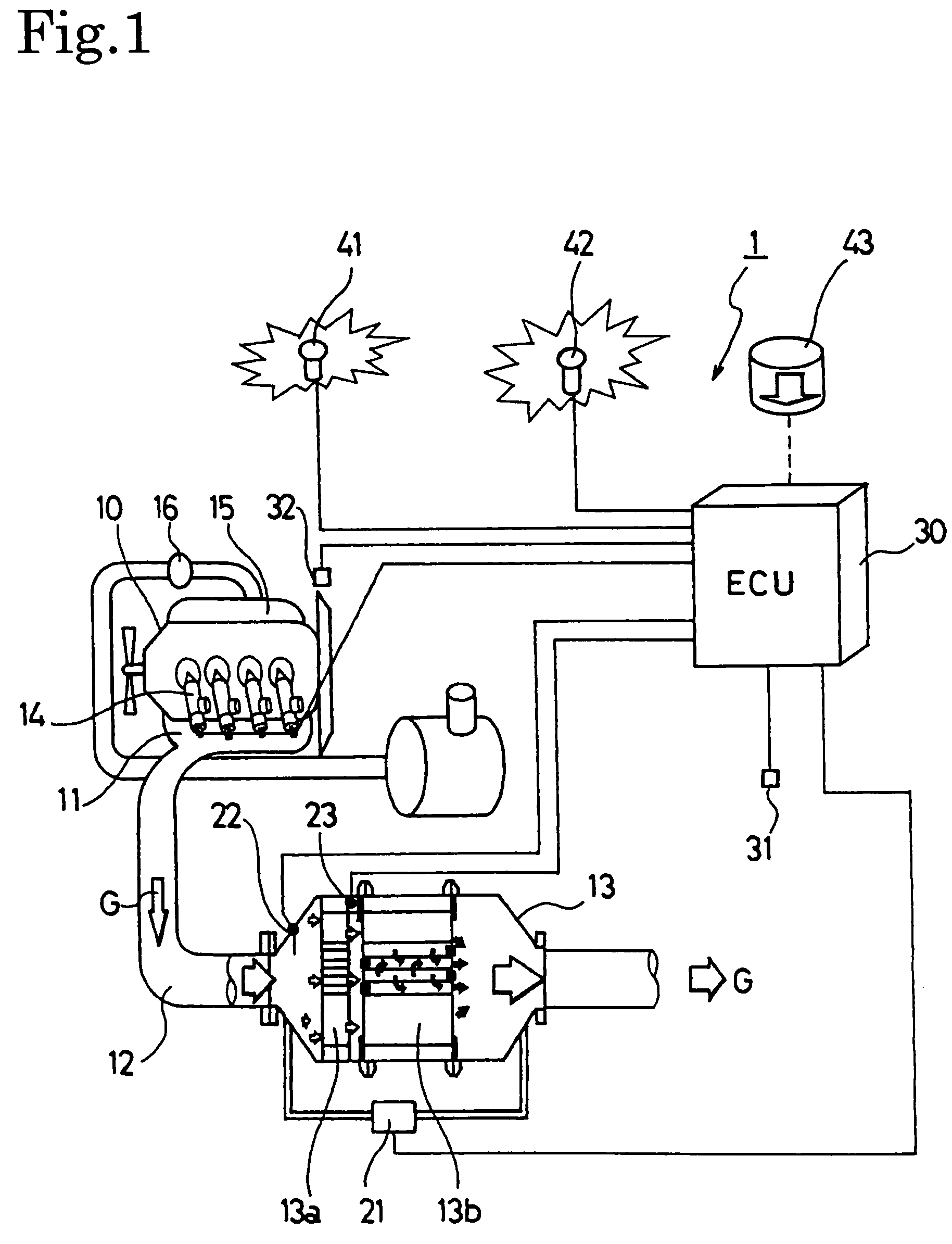
[0037]An explanation is given below of the exhaust gas purifying system according to the present invention while referencing the diagrams. This system is using an exhaust gas purifying system with a continuous regenerating DPF device structured in combination with an oxidation catalyst and a filter with catalyst.

[0038]The structure of the exhaust gas purifying system 1 of an internal combustion engine of this embodiment is shown in FIG. 1. The structure of this exhaust gas purifying system 1 comprises a continuous regenerating DPF 13 set up in the exhaust passage 12 which is connected to the exhaust manifold 11 of the diesel engine 10. This continuous regenerating DPF 13 is structured with an oxidation catalyst 13a on the upstream side and a filter 13b with catalyst on the downstream side.

[0039]This oxidation catalyst 13a is formed by supporting an oxidation catalyst such as platinum (Pt) with a support member having a porous ceramic honeycomb structure. The filter 13b with catalyst...


PUM


Abstract

An exhaust emission control system including a continuous regenerating diesel particulate filter (“DPF”) and a DPF controller, wherein a forced regenerator is operated by a driver's request, when it is judged that a traveling distance, after starting particulate matter collection, detected by a traveling distance detector has reached a predetermined judging traveling distance, even when the DPF controller detects that a collection amount detected by a collection amount detector is smaller than a prescribed judging collection amount. Accordingly, in a continuous regenerating DPF capable of manual regenerating, the number of warnings, such as a blinking regeneration button prompting a manual regeneration, is reduced to relieve a driver of annoyance or inconvenience.

Description

[0001]This application claims the benefit under 35 U.S.C. §371, of PCT International Application Number PCT / JP2005 / 020581, filed Nov. 10, 2005 and Japanese Application No. 2005-048309, filed Feb. 24, 2005, in Japan, the contents of which are incorporated herein by reference.FIELD OF THE INVENTION[0002]The present invention relates to an exhaust gas purifying system for purifying particulate matter with respect to the exhaust gases of an internal combustion diesel engine and the like by means of a continuous regenerating diesel particulate filter.DESCRIPTION OF THE RELATED ART[0003]Regulations for the amount of particulate matter (below called PM) discharged from a diesel engine have intensified year by year in addition to those for NOx, CO and HC. Technology has developed in which this PM is collected by a filter called a diesel particulate filter (below called DPF) and the amount of PM discharged to the outside is reduced.[0004]Types of DPF collecting this PM include wall-flow type...

Claims


Application Information

Patent Timeline
Patent Type & Authority Patents(United States)
IPC IPC(8): F01N3/00
CPCB01D53/944F01N3/0231F01N9/002F01N13/0097F01N2900/102F01N2900/1606Y02T10/47F02D41/024F02D41/029F02D41/402F02D41/405F02D2200/604Y02T10/40
Inventor SATOU, HITOSHIIMAI, TAKEHITOMASHIKO, TATSUOONODERA, TAKAOTAKEUCHI, MAKOTOKOMINE, MAMORUHIRAKI, NOBUYUKI
Owner ISUZU MOTORS LTD
Why Eureka
Try Eureka