Continuous motion case former

a technology of automatic case setup and case erection, which is applied in the field of automatic case setup and carton manipulation, can solve the problems of increasing complexity, increasing complexity, and increasing the duration and/or frequency of start stop operations associated, and achieves precise and rapid execution of highly repeatable operations. , the effect of reducing the duration and/or frequency of start stop operations

Inactive Publication Date: 2012-05-17
DOUGLAS MACHINE LIABILITY
View PDF9 Cites 24 Cited by
  • Summary
  • Abstract
  • Description
  • Claims
  • Application Information

AI Technical Summary

Benefits of technology

[0011]A case forming system, assemblies thereof, and attendant case forming processes are provided. Provisions are generally made to, among other things, eliminate, or at least minimize the duration and / or frequency of start stop operations associated with heretofore known case forming processes / apparatuses. Moreover, precise swiftly executed highly repeatable operations are sought for such process / system / apparatus.

Problems solved by technology

Variation in these regards from case to case may well render such cases unsatisfactory for use because such mechanized operations are dependent for proper operation in numerous respects on receiving cases only of the designated design configuration and dimensions, as well as those characterized by what oftentimes are tight processing tolerances.
A further and present reality is that the design of cases, cartons, containers, etc., and as a result, the design of mechanized processes and equipment for the formation of same, have become increasingly more sophisticated and complex.

Method used


Image

  • Continuous motion case former
  • Continuous motion case former
  • Continuous motion case former

Examples


Embodiment Construction

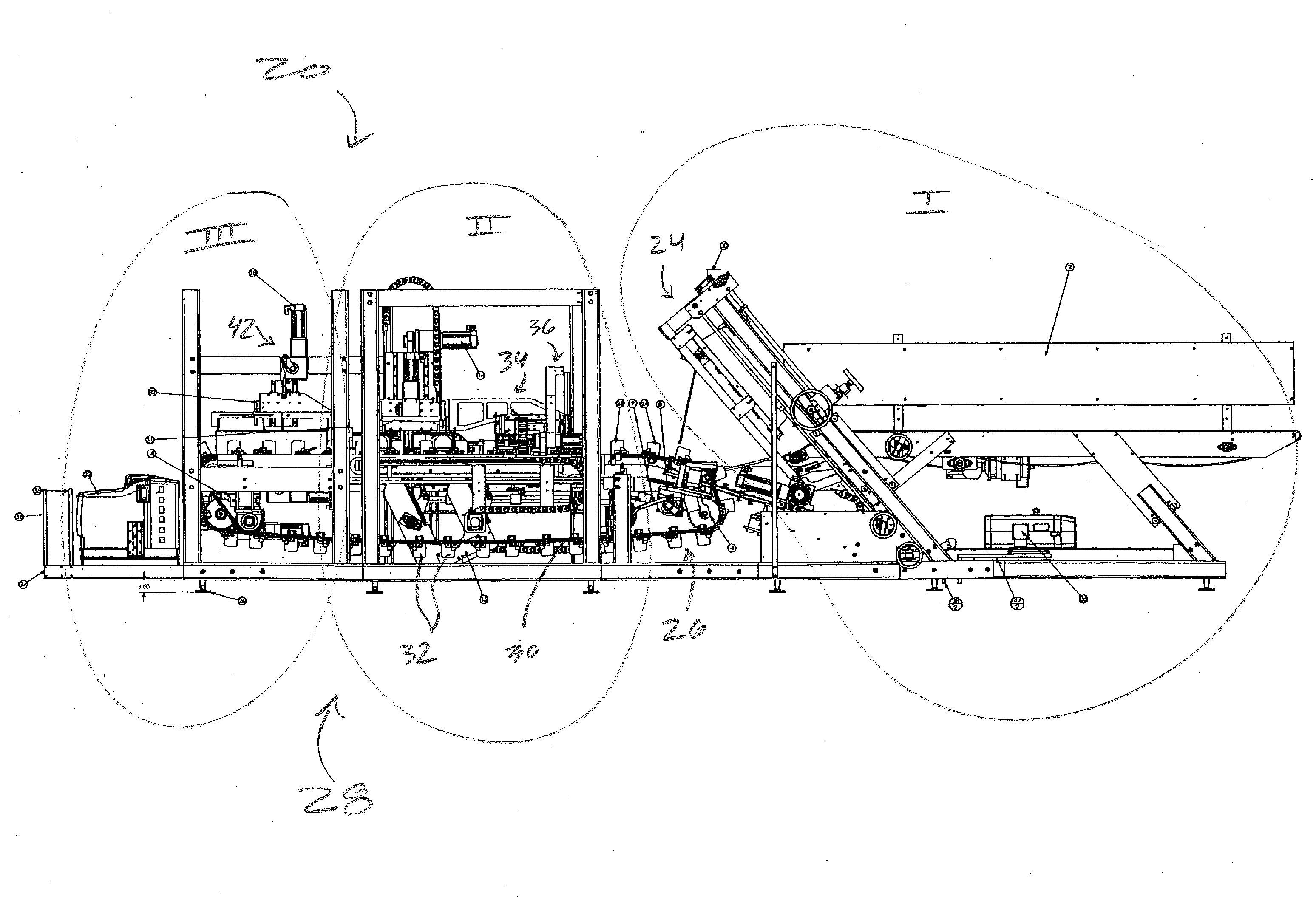
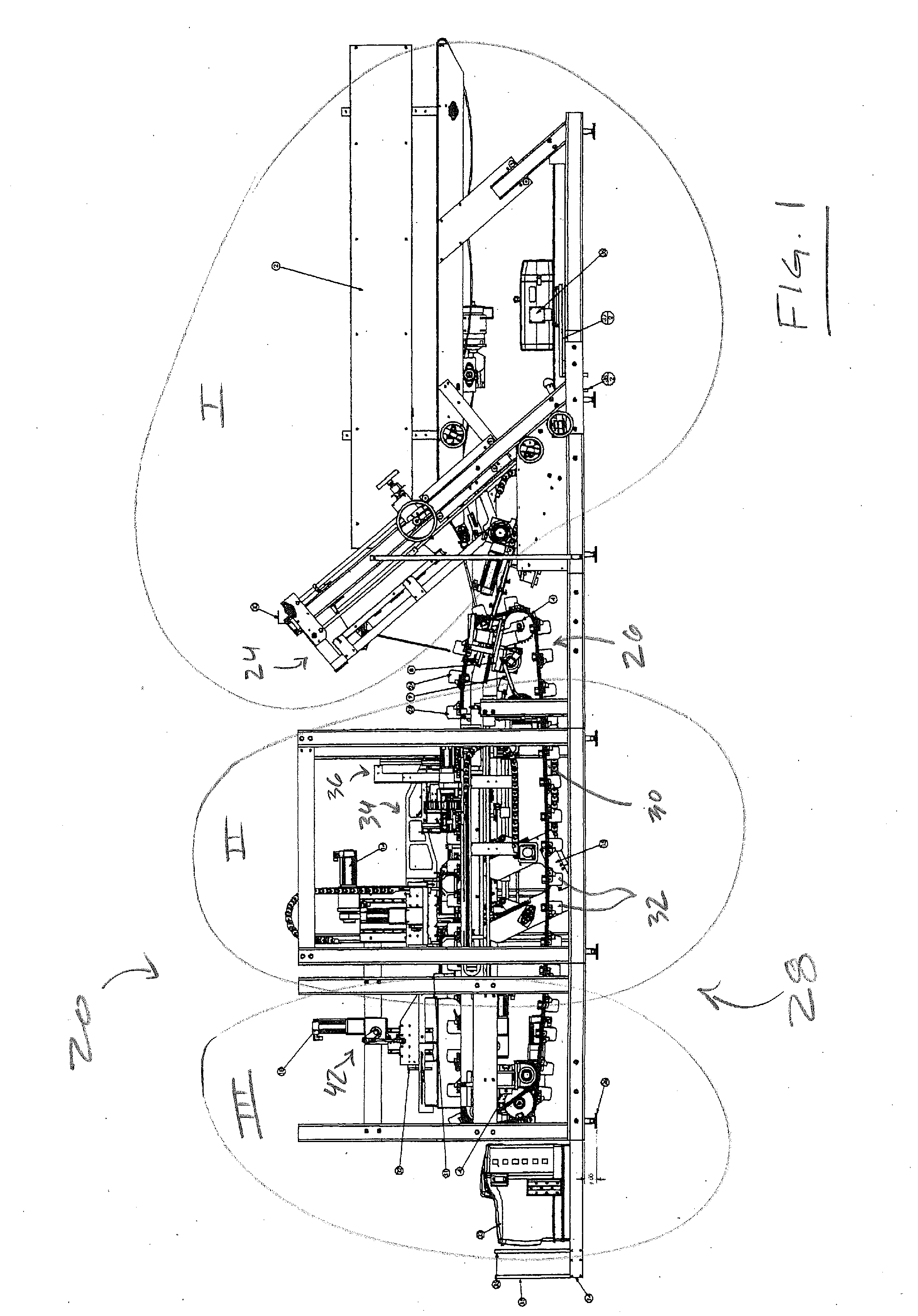
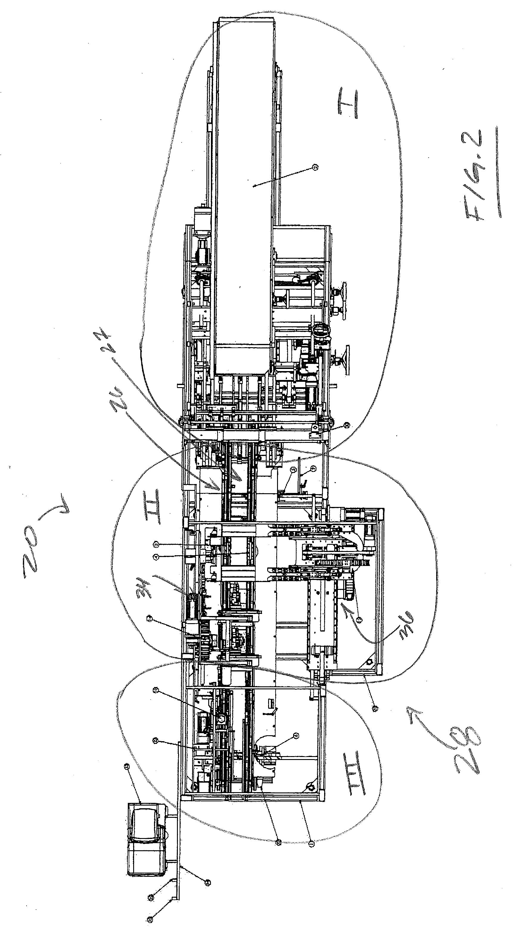
[0035]Advantageous, non-limiting systems, apparatus, devices, mechanisms, assemblies, subassemblies, structures, etc. are presented throughout the figures of the subject disclosure, namely FIGS. 1-18. By way of overview, a continuous motion case forming system is generally depicted in the alternate views, elevation and plan, of FIGS. 1 & 2, and thereafter, a variety of views of the continuous motion case former of the system of FIG. 1 are presented (FIGS. 3-7).

[0036]The balance of the figures, namely, FIGS. 8-18, are directed to select, assemblies, subassemblies or elements of or related to the former of FIG. 3, namely: a former ingress segment depicting spaced apart case precursors, i.e., those presented in an advantageous asymmetrical “U” shape configuration, and a movably mounted flap tucker assembly (FIG. 8); a traveling mandrel assembly (FIG. 9); the continuous motion case forming mandrel of FIG. 9 in two views (FIGS. 10 & 11), and alternate depictions, parts transparent / remove...


PUM


Abstract

Among other things, a case forming system is provided. The system includes a conveyance apparatus for conveying case precursors along a conveyance path and a case set-up apparatus characterized by a case forming member. Upstream case precursors are conveyed along the conveyance path for operation thereupon by the case forming member. A case forming mandrel of a mandrel assembly is movably mounted in relation to the conveyance apparatus for continuos motion with respect thereto. The continuous motion is delimited by travel of the case forming mandrel between an upstream locus and a downstream locus of the conveyance path, and reversible extension of the case forming mandrel towards case precursors during travel between the upstream locus and the downstream locus of the conveyance path.

Description

[0001]This is a United States national patent application filed pursuant to 35 USC §111(a) claiming priority under 35 USC §120 of / to U.S. Pat. Appl. Ser. No. 61 / 334,367 having a filing date of May 13, 2010 and entitled CONTINUOUS MOTION CASE FORMER, the disclosure of which is hereby incorporated by reference in its entirety.TECHNICAL FIELD[0002]The present invention generally relates to automated case or carton manipulations, and / or operations upon a case or carton precursor in furtherance of case formation, more particularly, to continuous motion automated case set-up and intermittent motion case folding / case erection, more particularly still, to any of systems, assemblies, apparatus, mechanisms, methods, etc. attendant to such continuous or intermittent motion automated case manipulations and / or operations upon a case precursor in furtherance of case set-up and formation.BACKGROUND OF THE INVENTION[0003]The automated erection of a case or carton from a source of case or carton pre...

Claims


Application Information

Patent Timeline
Patent Type & Authority Applications(United States)
IPC IPC(8): B31B3/00B31B50/28
CPCB31B1/00B31B2201/27B31B2201/2683B31B2201/2608B31B50/00B31B50/003B31B50/30B31B50/58
Inventor PAZDERNIK, IRVAN L.LENARZ, JEFFERY L.THOEN, RANDY K.ANDERSON, PAULLARSON, MARK
Owner DOUGLAS MACHINE LIABILITY
Why Eureka
Try Eureka