
Work light structure
a technology for working light and structure, applied in fixed installation, lighting and heating apparatus, lighting support devices, etc., can solve the problems of limiting the use of the workshop, the inability of the lamp to light the required area, and the maintenance of the lamp, so as to enhance the versatility of functions and facilitate carrying and storage.
- Summary
- Abstract
- Description
- Claims
- Application Information
AI Technical Summary
Benefits of technology
Problems solved by technology
Method used
Image

Examples
Embodiment Construction
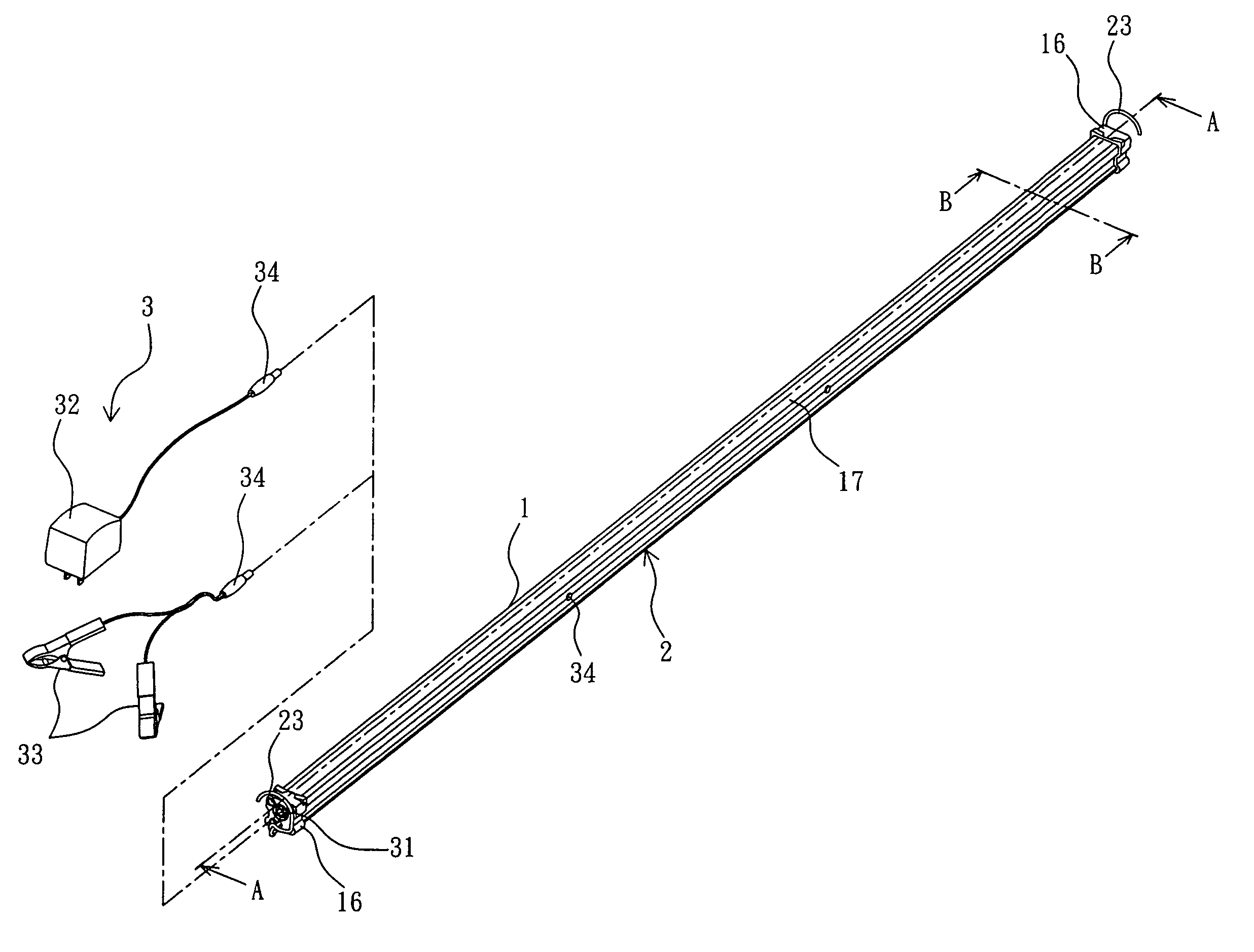
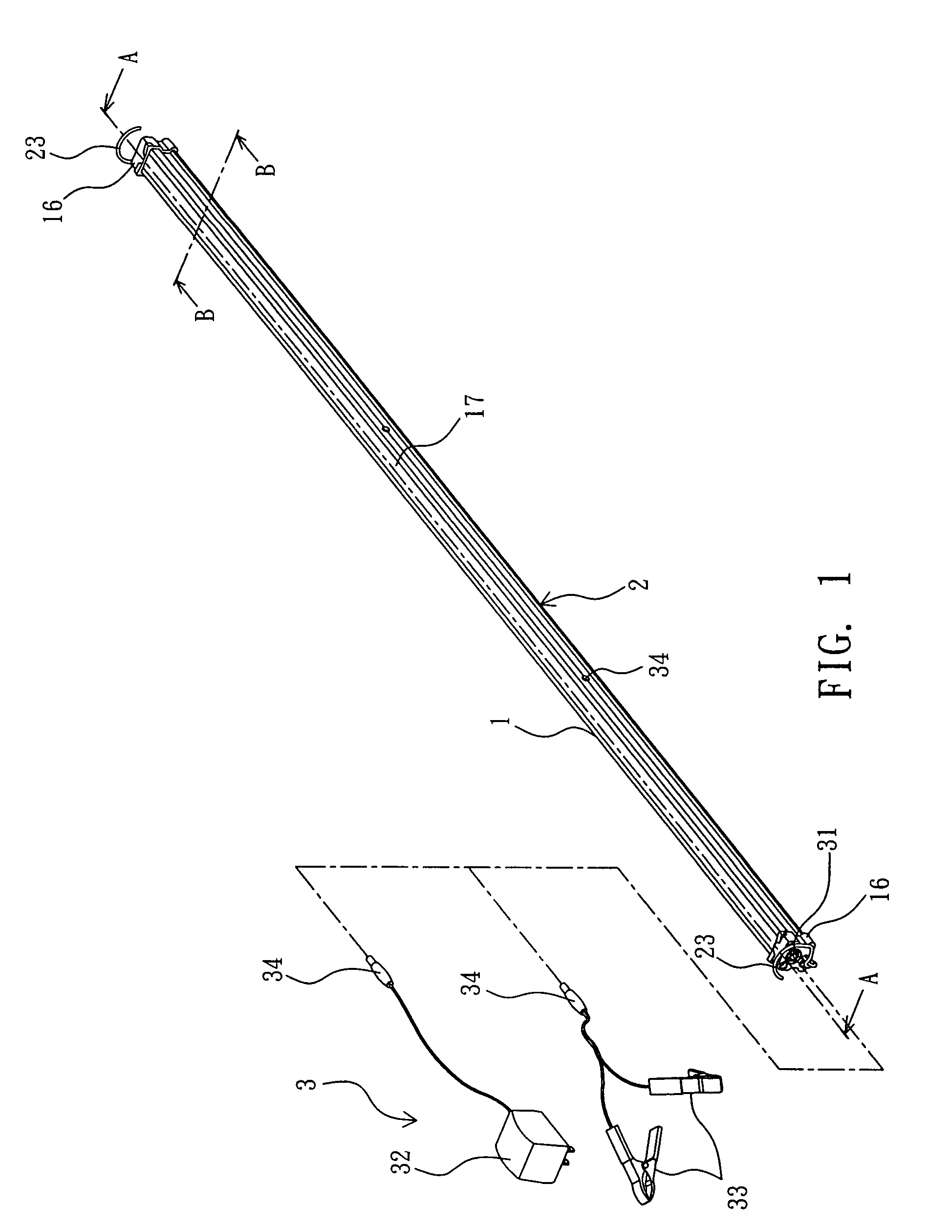
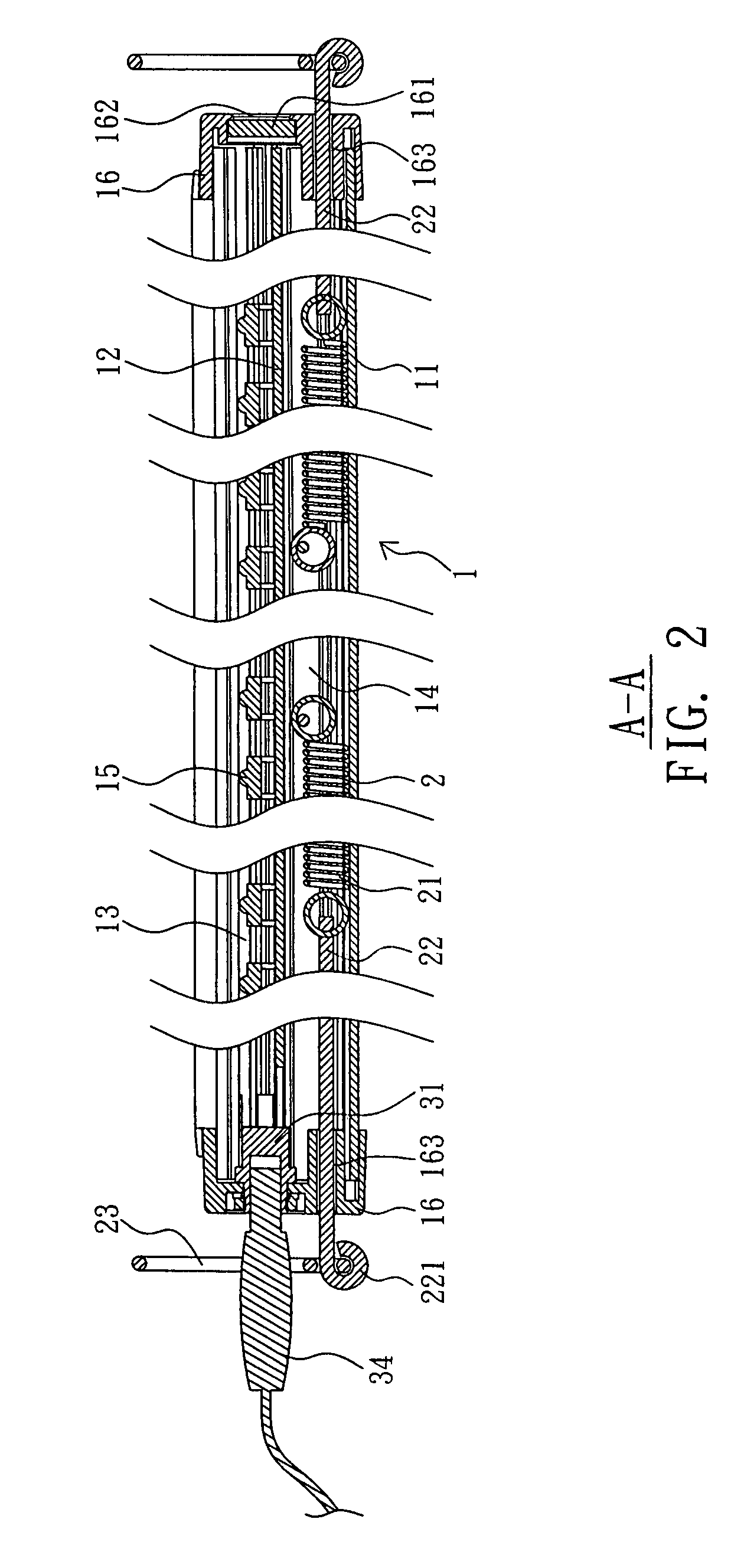
[0025]With reference to FIGS. 1 to 3, a work light according to the present invention comprises a light source module 1 and an extension device 2, wherein the light source module 1 comprises a long slender housing 11 formed by extruding of aluminum or injection molding of plastics, for example, and laterally connected a printed circuit board 12 which is also a shape of long slender such that the housing 11 is partitioned into a lighting portion 13 and an accommodating portion 14. The printed circuit board 12 is coupled with a plurality of light emitting diodes (LEDs) 15 arranged in line inside the lighting portion 13, and the accommodating portion 14 is reserved for the extension device 2 described later. When the light source module 1 is assembled, each of the two ends of the housing 11 is connected with an end cap 16, respectively, for capping the ends, wherein one of the end caps 16 is disposed with a power supply device 3, a battery for example, for supplying power to enable the...
PUM
 Abstract
Description
Claims
Application Information