Seal member for a vibrating screed

a technology of sealing member and vibrating screed, which is applied in the direction of roads, roads, highways, etc., can solve the problems of blade movement undesired, blade joint damage, and unfavorable use by users, so as to avoid undesired blade movement

Active Publication Date: 2009-06-23
MAGIC SCREED 9033 4624 QUEBEC
View PDF20 Cites 4 Cited by
  • Summary
  • Abstract
  • Description
  • Claims
  • Application Information

AI Technical Summary

Benefits of technology

[0022]In an embodiment, the vibration-causing assembly comprises a shaft assembly and a bearing assembly in communication with the shaft assembly for substantially avoiding undesired movement of the blade during the vibratory motion. In an embodiment, the bearing assembly comprises a double bearing assembly. In an embodiment, the double bearing assembly comprises a first bearing mounted to one end of the shaft assembly and a second bearing mounted to an opposite end of the shaft assembly. In an embodiment, the first bearing is mounted between two shoulder structures formed at one end of the shaft assembly and the second bearing is mounted between another two shoulder structures formed at an opposite end of the shaft assembly.

Problems solved by technology

A drawback of the prior art is that the junction between the actuator and the vibration-causing assembly is often damaged by concrete accidentally entering this junction during the surfacing operation.
Another drawback of the prior art vibrating screeds is that the vibration-causing device causes undesired movements to the blade that do not allow for smooth surfacing.
A further drawback of the prior art is that the handles are not of a convenient height for a variety of users.

Method used


Image

  • Seal member for a vibrating screed
  • Seal member for a vibrating screed
  • Seal member for a vibrating screed

Examples


Embodiment Construction

[0038]With reference to the appended drawings embodiments of the invention will be herein described so as to exemplify the invention only and by no means limit the scope thereof.

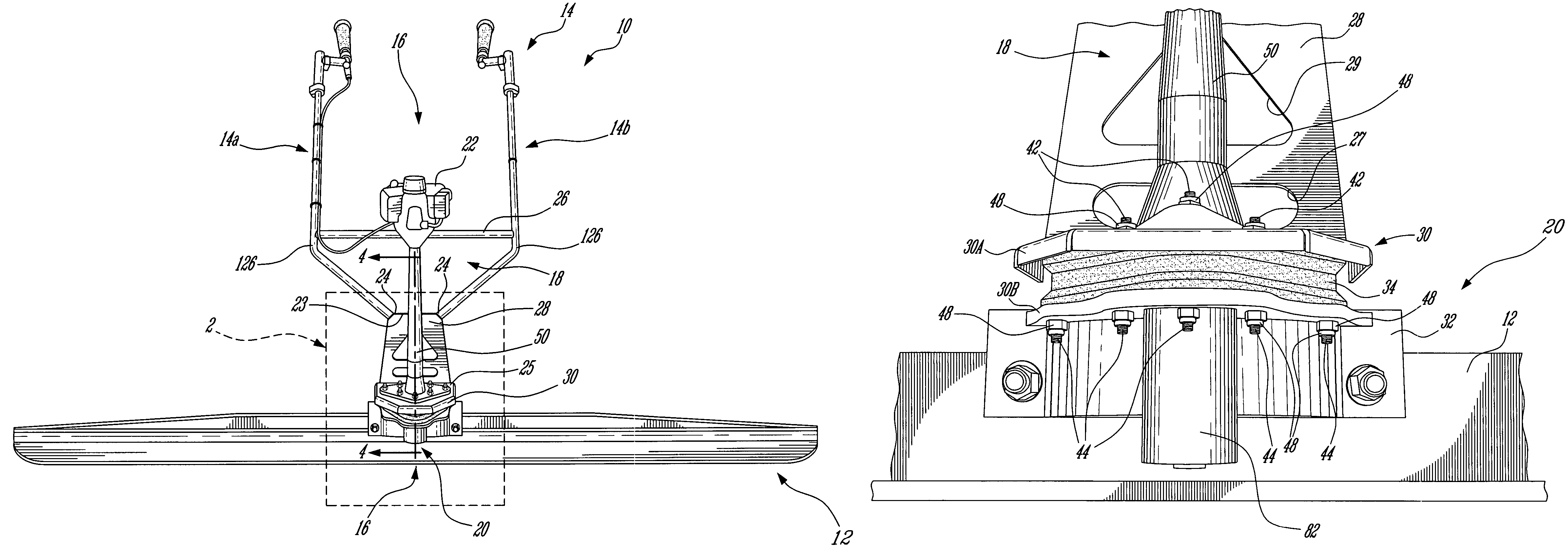
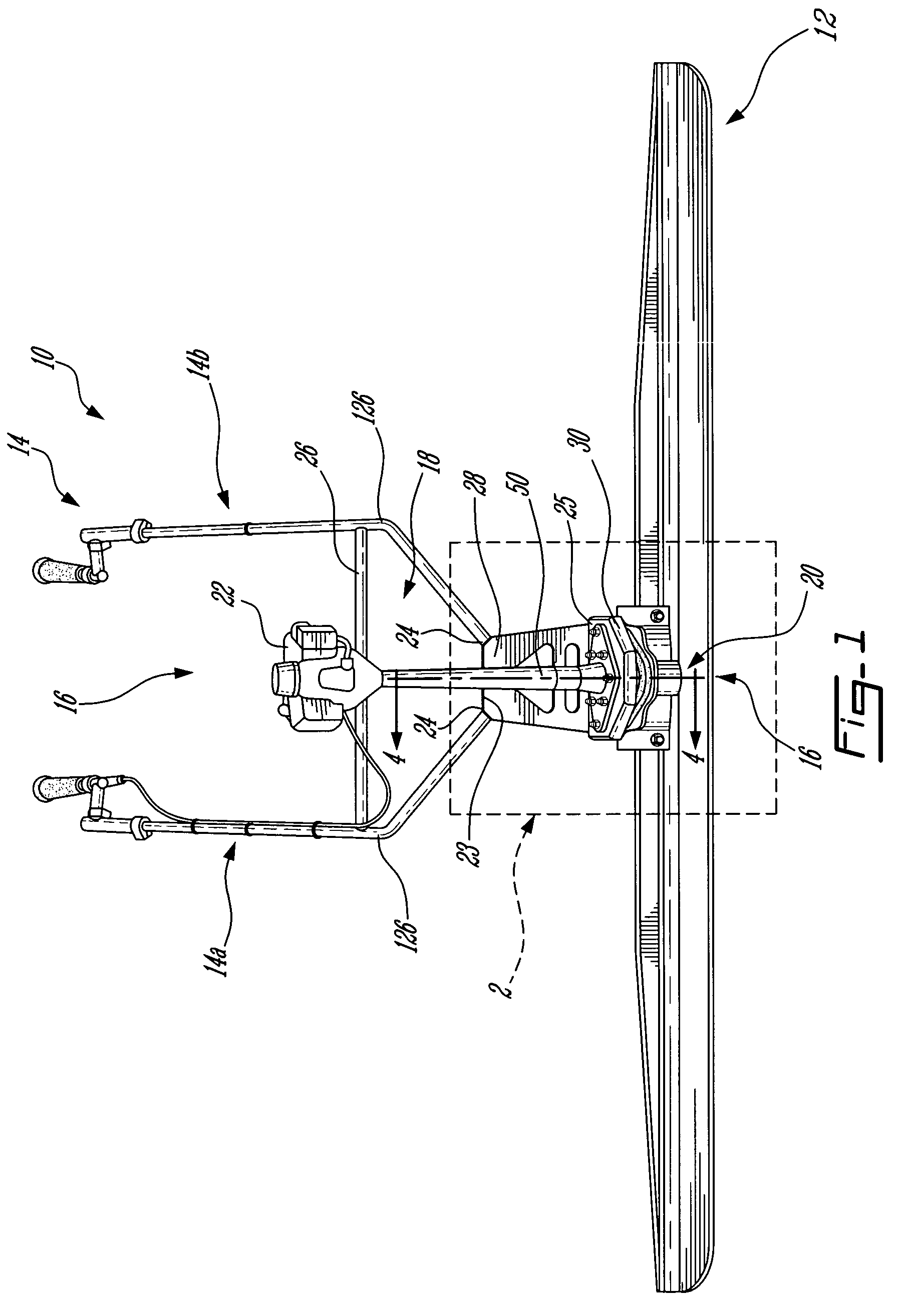
[0039]FIG. 1 illustrates a vibrating device or vibrating screed 10 in accordance with an embodiment of the present invention.

[0040]Apart from the invention disclosed and the various embodiments thereof, vibrating screed 10 bears some similarity to the vibrating screed of U.S. Pat. No. 6,296,467, which is incorporated herein by reference.

[0041]The vibrating screed 10 comprises an elongated surfacing blade 12, a steering assembly 14 in communication with the blade 12, an actuator / vibration-causing assembly 16 in communication with blade 12 for imparting a vibratory motion thereto, as will be described herein, such that, when the blade 12 is displaced over a not yet set concrete surface (not shown), it surfaces or smoothens, this concrete surface.

[0042]The actuator / vibration-causing assembly 16 includes an actu...


PUM


Abstract

A vibrating device for surfacing concrete comprising a surfacing blade, a vibration-causing assembly in communication with the surfacing blade and an actuator in communication with the vibration-causing assembly so as to cause the vibration-causing assembly to impart a vibratory motion to the blade. A seal member is mounted about the junction between the actuator and the vibration-causing assembly. The said seal member seals the junction from concrete during surfacing.

Description

CROSS REFERENCE TO RELATED APPLICATIONS[0001]This application claims priority on Canadian Patent Application CA 2,475,525 filed on Jul. 22, 2004, which is incorporated herein by reference.FIELD OF THE INVENTION[0002]The present invention relates to vibrating devices or screeds. More specifically the present invention relates to an improved vibrating screed. Still more specifically, the present invention relates to a seal member for a vibrating device.BACKGROUND OF THE INVENTION[0003]Vibrating devices and more particularly vibrating screeds for surfacing concrete are known in the art, these devices include an elongated surfacing blade mounted transversally at the bottom of a pair of hand-held steering handles with an actuator, such as a motor being adapted to transmit to the blade a vibratory motion. Usually, the motor acts on a vibration-causing device, which is in communication with the blade to impart this vibratory motion.[0004]Examples of such devices inlcude U.S. Pat. No. 4,861...

Claims


Application Information

Patent Timeline
Patent Type & Authority Patents(United States)
IPC IPC(8): E01C19/38
CPCE01C19/402E04F21/242
Inventor ROUILLARD, ROGER
Owner MAGIC SCREED 9033 4624 QUEBEC
Why Eureka
Try Eureka