Erection system

a technology of elongation and elongation, which is applied in the direction of load-engaging elements, building materials handling, construction, etc., can solve the problems of difficult access to the upper portion of the element to disconnect the lifting line, difficulty in accessing the lifting line, and causing certain safety concerns

Active Publication Date: 2018-02-13
BONGIORNO STEVEN JAMES
View PDF35 Cites 6 Cited by
  • Summary
  • Abstract
  • Description
  • Claims
  • Application Information

AI Technical Summary

Benefits of technology

[0010]The lower support piece holds the vertical weight of the element while ensuring lateral restraint for stability and positioning of the lower portion or the element. See FIGS. 26A-27B for diagrammatic illustration. This lower support piece supports the vertical weight of the element by connection to a removable loadbearing piece, preferably an internally threaded loadbearing nut, located below the support piece, while allowing for free movement of the lifting bar in the longitudinal direction away from the upper support piece during installation of the lifting bar. This loadbearing piece is attached to the lifting bar which in turn supports the vertical weight axially to the lifting device. The removable loadbearing nut allows for disconnection of the lifting bar to be done at the lower portion of the element. The loadbearing nut is preferably threaded onto the lifting bar to facilitate installation and removal, and also to permit for vertical adjustment of the elevation of the support point of the lifting bar against the lower support piece.
[0011]The upper support piece provides lateral restraint to the upper portion of the element against the lifting bar, ensuring lateral stability of the element. See FIGS. 26A-27B for diagrammatic illustration. The upper support piece may optionally be provided with a stop piece, preferably a loadbearing nut or plate, located above the upper support piece to prevent undesired movement of the lifting bar toward the lower support piece, while allowing for free movement of the lifting bar in the longitudinal direction away from the lower support piece during extraction of the lifting bar.
[0012]The support pieces are preferably comprised of steel brackets or loadbearing frames preferably made of axially extending members preferably made of steel. The support pieces are provided with at least one aperture for receiving the at least one lifting bar. The size of the aperture being complimentary to the size of the lifting bar and being large enough to allow free movement of the lifting bar through it, while being small enough that to provide adequate lateral restraint described previously. Where the apertures are larger than desired to achieve this, the annular space between the lifting bar and the aperture can be reduced with the use of a bushing or makeup sleeve.
[0017]The lifting bars are comprised preferably of steel bars preferably with external threading along at least a portion of its length to accept a loadbearing nut having complimentary internal threading. The loadbearing nut is preferably provided with a temporary holding means comprised preferably of a spring clamp, but alternatively may be provided with a standard set screw. The upper end of the lifting bar is provided with a preferably steel lifting collar onto which a preferably steel lifting ring, or hook eye, is attached for rigging to the lifting lines. The lifting collar is preferably located in close proximity to the top of the upper support piece to reduce the projected length of the bar between the upper support pieces and the lifting collar, thus minimizing undesirable lateral and bending stresses in the lifting bar.
[0018]Where more than on lifting bar is used, they may be provided with a spreader piece, such as an adjustable spreader bar oriented perpendicular to the longitudinal axis of the lifting bars to resist the horizontal force resulting for example from the lifting lines acting at an angle to the longitudinal axis of the lifting bars. See FIGS. 24A-25B for diagrammatic illustration. The spreader bar thus minimizes undesirable lateral and bending stress in the lifting bar and maintains lateral separation between the top portions of the lifting bars during installation and after they have been extracted.

Problems solved by technology

In some cases, especially where the element is tall, it is difficult to access the upper portion of the element to disconnect the lifting lines.
Doing so may also pose certain safety concerns.
However, this results in a condition where the pivot point is located below the center of gravity of the element.
This results in a naturally unstable condition, such as the case of an inverted pendulum.

Method used


Image

  • Erection system
  • Erection system
  • Erection system

Examples


Embodiment Construction

[0106]The subject of the present invention will now be described, with reference to the accompanying drawings shown in FIGS. 1-23. Where similar components are shown in multiple figures, the respective description of the parts may not be repeated.

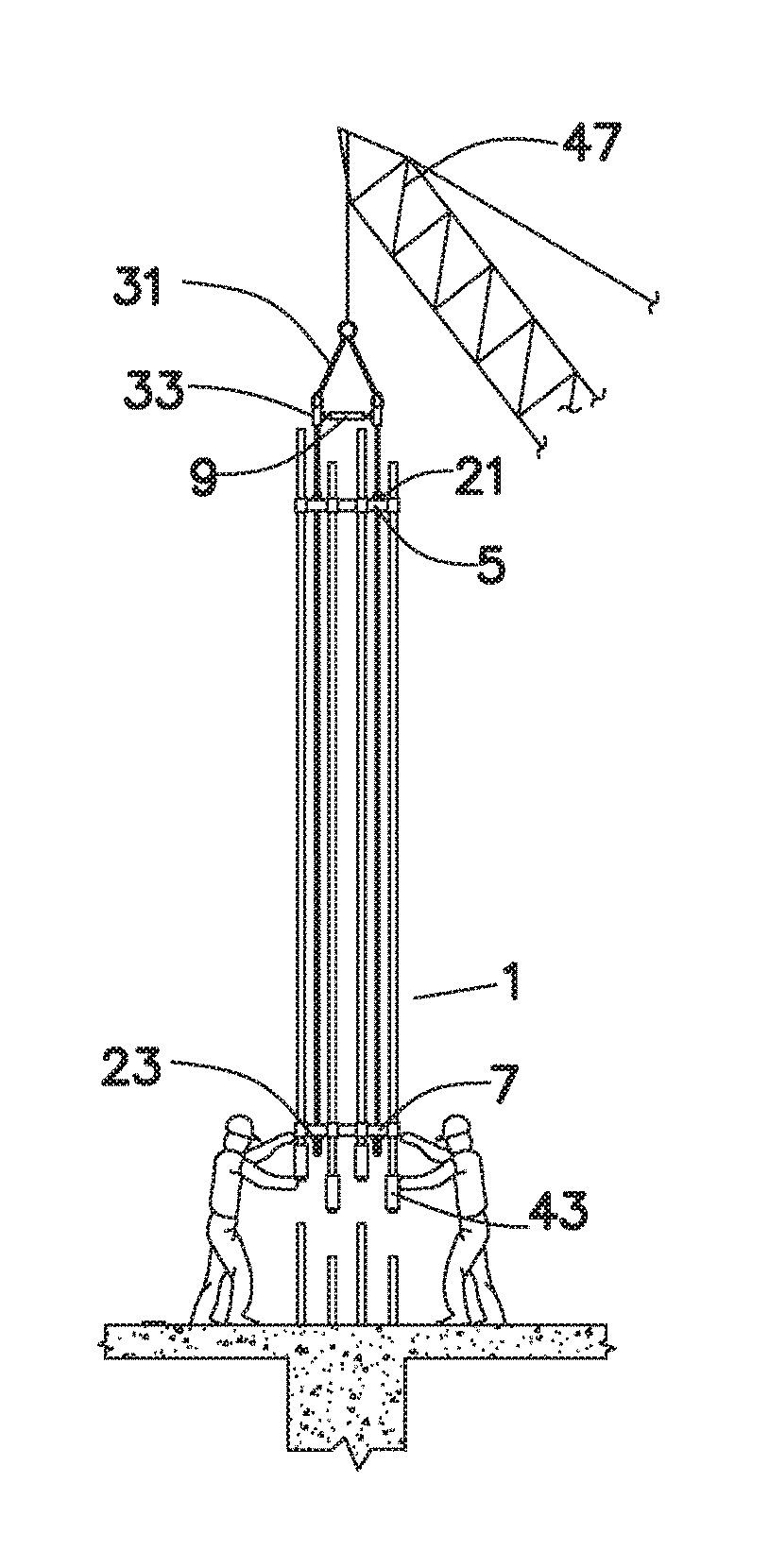
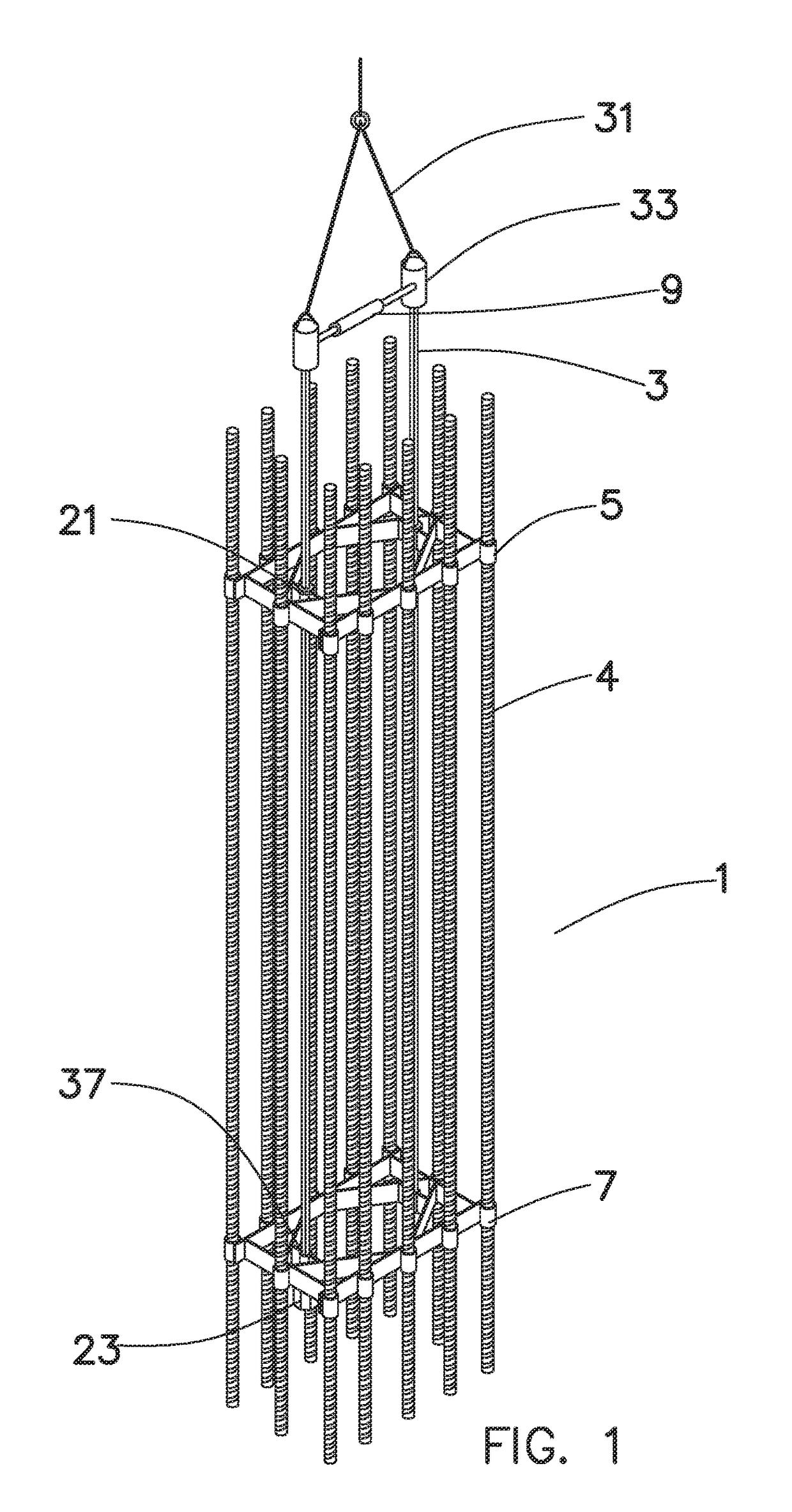
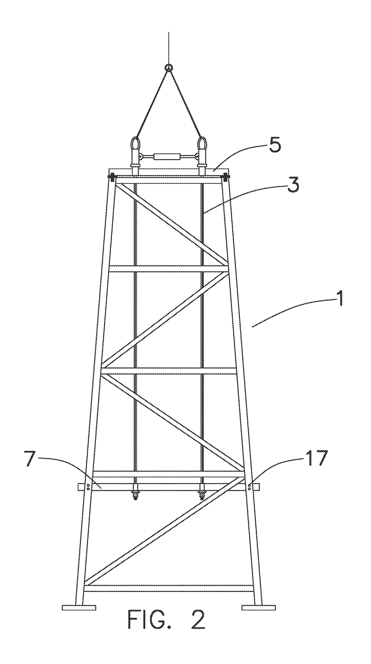
[0107]Referring to FIGS. 1-6, the elongated element (1) of the present invention is provided with at least two support pieces (5&7) spaced apart from each other. One of the at least two support pieces (5) is preferably located at the upper portion of the element (1), and one of the at least two support pieces (7) is preferably located at the lower portion of the element (1). Additional support pieces may optionally be placed between said upper (5) and lower (7) support pieces. The elongated element (1) is further provided with at least one lifting bar (3) that is inserted through each of the at least two support piece (5&7) and connected to said support piece to provide the vertical and lateral stabilizing restraint for the elongated elemen...


PUM


Abstract

An erection system for one or more elongated elements, such as structural columns, pre-fabricated reinforcing cages or tower-like structures includes one or more longitudinal lifting bars running parallel with the elongated element's longitudinal direction. The lifting bars are installed within or onto the elongated element through apertures in the element's upper and lower support pieces. A rigging system supports the upper portion of the lifting bar. The lifting bar's lower portion includes external threading to receive an internally threaded load bearing nut. The load bearing nut supports the elongated element's weight onto the lifting bar's lower portion. The upper and lower support pieces stabilize the elongated element with lateral restraint. Removing the load bearing nut and raising the lifting bar up through the support piece's apertures extracts the lifting bar from the elongated element. Adjustable spreader bars separate multiple lifting bars to minimize lateral and bending stresses in the lifting bar.

Description

[0001]I have invented a new method and apparatus for erecting elongated elements, or assemblies of elements.FIELD OF THE INVENTION[0002]The present invention relates to the erection of elongated elements, or assemblies of elements, such as performed during construction, in a safe and efficient manner.BACKGROUND OF THE INVENTION[0003]The present invention relates to construction technologies. In particular, the present invention relates to the lifting and installation of elongated elements, or assemblies of elements, such as for example, steel columns, precast concrete columns, prefabricated reinforcing cages, and tower-like structures, to name a few. Examples of prefabricated reinforcing cages are shown in the patents Ferrer (U.S. Pat. No. 8,381,479), Hasak (U.S. Pat. No. 4,467,583) and Bongiorno (U.S. Pat. No. 9,267,287). Examples of tower-like structures are shown in the patents of Fang (U.S. Pat. No. 9,038,348) and Murata (U.S. Pat. No. 8,209,913). The present invention provides ...

Claims


Application Information

Patent Timeline
Patent Type & Authority Patents(United States)
IPC IPC(8): E04G21/16E04C5/06B66C1/10B66C1/62E04C5/16E04B1/18
CPCE04G21/16E04B1/18E04C5/0622B66C1/10B66C1/62E04C5/16E04C5/0618E04C5/0604E04G21/142E04G21/12
Inventor BONGIORNO, STEVEN JAMES
Owner BONGIORNO STEVEN JAMES
Why Eureka
Try Eureka