Jewelry Device

Inactive Publication Date: 2007-05-31
AZAR PETRA
View PDF10 Cites 6 Cited by
  • Summary
  • Abstract
  • Description
  • Claims
  • Application Information

AI Technical Summary

Benefits of technology

[0008] The size of each member can be completely different. For example, a full circle having a width of about 3 cm can be attached to a slim crescent moon of 5 mm in width for attachment to the side of the circle. This way, pavé diamonds and gold could be easily combined. Thus, the requirement that the members are matched in size is eliminated. Materials can be combined in the most unusual ways such as rubber and steel with the result of obtaining a homogenous piece once the members are connected, reflecting that theme that two individuals become one.
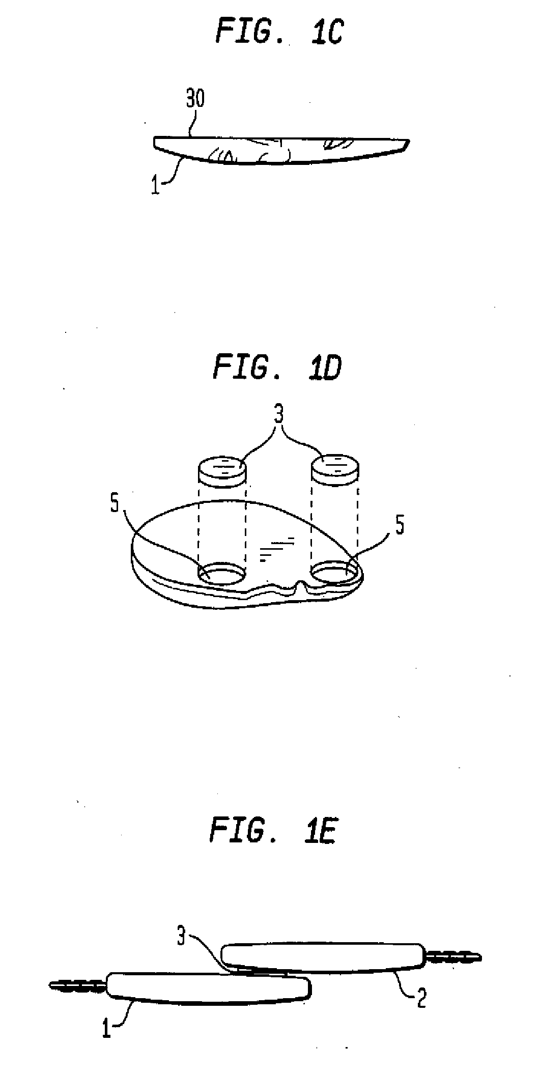
[0011] In another embodiment of the connecting means, in addition to the magnets, each member is provided with means for connecting with the complementary member in addition to the magnet. Such means are for example a pin or pins which are located at one of the members preferably at the complementary portion of the member for placing into a pin hole or holes located at the complementary portion of the other member. Variations of the pin and pin hole are such that each member is provided with a hole and a pin for connecting to the other member provided with a hole and a pin for interconnecting with that other member. The pin and hole system provides additional stability to the magnetic connection. This stabilization is desirable especially also for larger pieces, as the pin and hole connection prevents undesired movement of one of the members relative to the other and the members will be held flush against each other.
[0022] Another feature of the device according to the present invention is that the connected split jewelry device is attached to a chain, preferably at the outer lateral portions of the two members. In the case where the medallion is worn as a necklace, the interconnected split medallion acts as a convenient front closure of the device and thus eliminating the need for a clasp in the back of the chain and also eliminates the need for a bail, normally needed as a link between the pendant and the chain.

Problems solved by technology

These jewelry pieces are often formalized and do not allow free-flowing shapes to be included.

Method used


Image

  • Jewelry Device
  • Jewelry Device
  • Jewelry Device

Examples


Embodiment Construction

[0051] Throughout all the Figures, same or corresponding elements are generally indicated by same reference numerals. These depicted embodiments are to be understood as illustrative of the invention and not as limiting in any way. It should also be understood that the drawings are not necessarily to scale and that the embodiments are sometimes illustrated by graphic symbols, phantom lines, diagrammatic representations and fragmentary views. In certain instances, details which are not necessary for an understanding of the present invention or which render other details difficult to perceive may have been omitted.

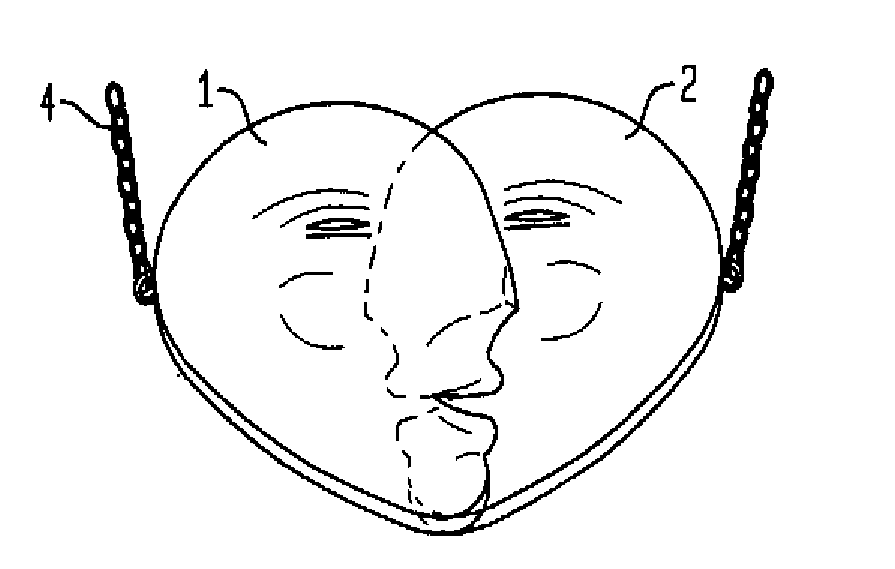
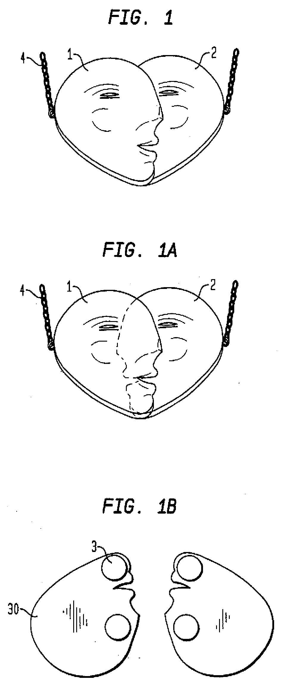
[0052] Turning now to the drawing, and in particular to FIG. 1, there is shown an interconnected split medallion jewelry device with two members 1 and 2. The two members 1, 2 are shown as sculpted faces overlapping with each other and forming a heart shape. The overlap is seen in FIG. 1a as a broken line.

[0053]FIG. 1b shows the same embodiment from the reverse side 30 with ...


PUM


Abstract

A sculpted interconnected split jewelry device is connected in a variety of ways through magnets that are placed in recesses where the connection is invisible from the outside; and wherein a stabilizing system is provided in the members of the device.

Description

CROSS-REFERENCES TO RELATED APPLICATIONS [0001] This application is a continuation-in-part of prior filed copending application Ser. No. 11 / 225,566, filed Sep. 13, 2005.BACKGROUND OF THE INVENTION [0002] The present invention relates to a jewelry device and in particular a device that includes a jewelry design that is split in two ore more pieces whereby the pieces are reconnected by connecting means, the device to be worn as a necklace, pendent, bracelet, belt buckle or any other type jewelry in which an ornamental, sculpted jewelry piece is made up of interconnected pieces for attachment and detachment from each other. [0003] All types of jewelry are known in the prior art. Sculptured pieces are known in the prior art in form of three dimensional pieces, cameos and the like. Medallions and sculpted items can be made of all types of metal or may be carved from natural occurring material such as precious stones, semi-precious stones, shells or synthetic material. Another form of jew...

Claims


Application Information

Patent Timeline
Patent Type & Authority Applications(United States)
IPC IPC(8): A44C5/00
CPCA44C3/007A44D2203/00
Inventor AZAR, PETRA
Owner AZAR PETRA
Why Eureka
Try Eureka