Versatile maskless lithography system with multiple resolutions

Inactive Publication Date: 2006-01-19
ANVIK CORP
View PDF0 Cites 93 Cited by
  • Summary
  • Abstract
  • Description
  • Claims
  • Application Information

AI Technical Summary

Benefits of technology

[0009] This invention provides a capability for selecting rapidly among a plurality of projection lenses in a maskless patterning system, providing multiple choices for resolution and feature size, and enabling optimization of the combination of the imaging resolution and exposure throughput.

Problems solved by technology

These factors can be particularly significant for electronic components manufactured in low volumes, such as many military electronics, where mask-related issues may be the primary influences affecting the price and delivery of the component.

Method used


Image

  • Versatile maskless lithography system with multiple resolutions
  • Versatile maskless lithography system with multiple resolutions
  • Versatile maskless lithography system with multiple resolutions

Examples


Embodiment Construction

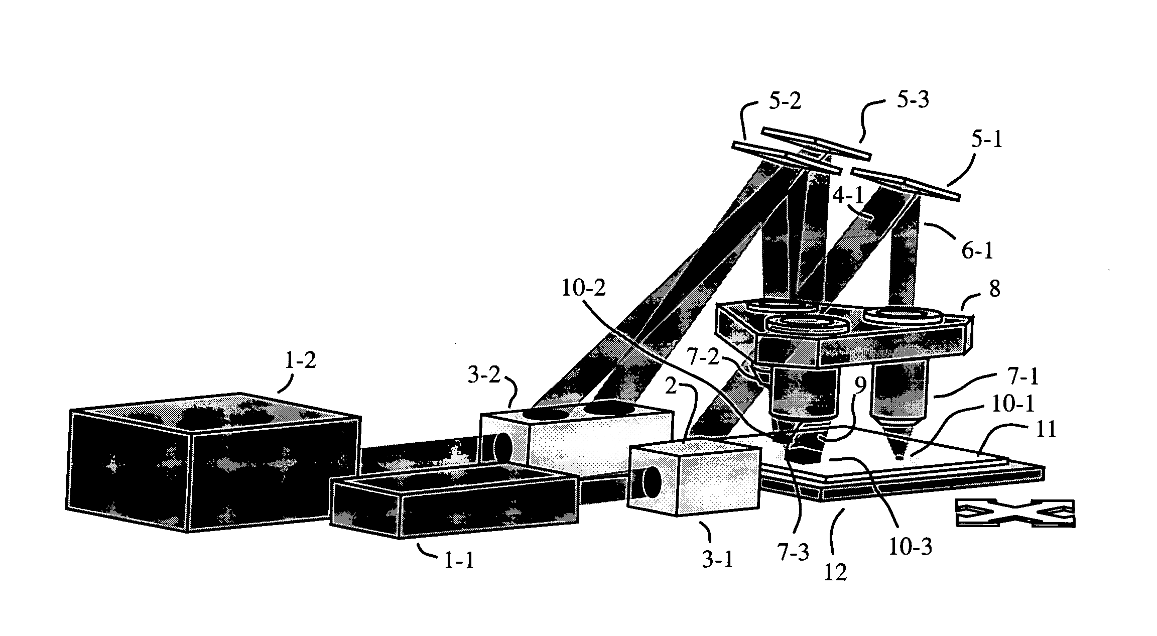
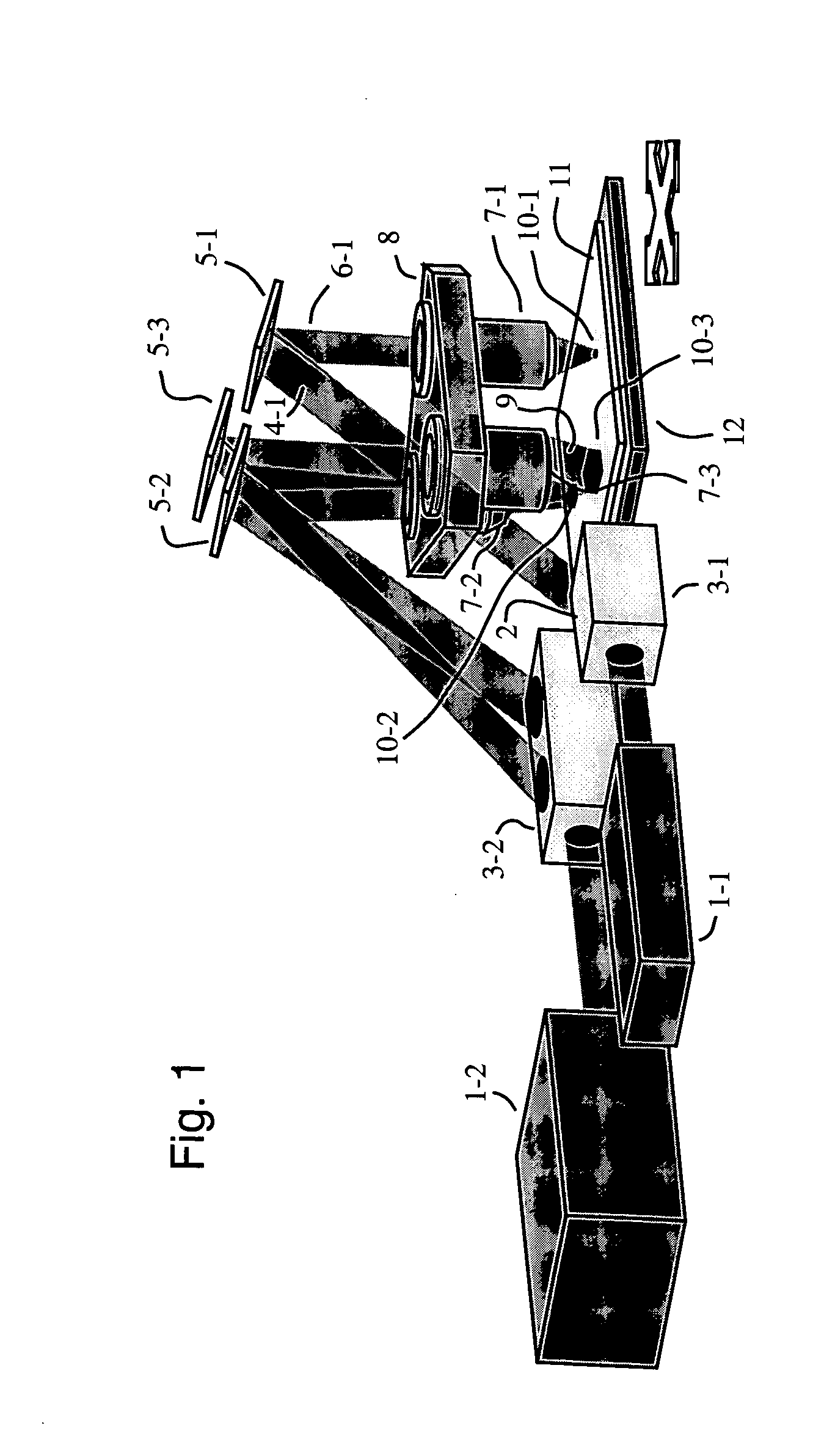
[0029]FIG. 1 shows an overview of the versatile maskless patterning system. Radiation is provided by collimated light sources 1-1 and 1-2, which could be excimer lasers or other types of pulsed laser source. The beams of light 2-1 and 2-2 are directed through an illumination systems 3-1 and 3-2 that transform and split the non-uniform output beams of the lasers into a highly uniform beams 4-1, 4-2 and 4-3 that are shaped to match the entrance apertures of spatial light modulators (SLMs) 5-1, 5-2, and 5-3. SLMs 5 could be a digital micromirror device (DMD) arrays used in reflection or it could be a liquid crystal light valves used in transmission. The spatially modulated beams 6-1, 6-2, and 6-3 of light emerging from SLMs 5 is then directed through projection lenses 7-1, 7-2, and 7-3 mounted on lens mount 8 to form a focused beams 9-1, 9-2, and 9-3 that form demagnified images 10-1, 10-2, and 10-3 on substrate 11. Substrate 11 is mounted on planar scanning stage 12 that is capable of...


PUM


Abstract

A versatile maskless patterning system with capability for selecting rapidly among a plurality of projection lenses mounted on a turret. This provides the ability to rapidly select multiple choices for resolution and enables optimization of the combination of the imaging resolution and exposure throughput, making possible cost-effective fabrication of microelectronics packaging products. A preferred embodiment uses a digital micromirror device array spatial light modulator as a virtual mask. Another preferred embodiment use multiple closely spaced digital micromirror device array spatial light modulators to enhance throughput.

Description

BACKGROUND OF THE INVENTION [0001] (1) Field of the Invention [0002] This invention relates to a versatile maskless patterning system with capability for: selecting rapidly among a plurality of projection lenses, providing multiple resolutions, enabling optimization of the combination of the imaging resolution and exposure throughput, and making possible cost-effective fabrication of microelectronics packaging products. [0003] (2) Description of Related Art [0004] Microelectronic packaging technology is a key driver leading to advancements in the performance of electronic systems that are integrated on circuit boards. Especially for high-processing-power systems, the packages may be the most crucial factor since they gate the rate of communication between different chips, and in fact, a high-end processor may be only as good as the packages that are used to interface it with the other components on the board. Additionally, given the importance of portability for commercial, but espe...

Claims


Application Information

Patent Timeline
Patent Type & Authority Applications(United States)
IPC IPC(8): G03B27/54
CPCG03F7/70291G03F7/70275
Inventor KLOSNER, MARC A.JAIN, KANTI
Owner ANVIK CORP
Why Eureka
Try Eureka