Air re-circulation effect reduction system

a technology of air recirculation and effect reduction, which is applied in the field of air recirculation effect reduction system, can solve the problems of reducing the efficiency at which the computer system is cooled, reducing the efficiency at which the air conditioning unit operates, and typically dispersing relatively significant amounts of heat in the computer system, so as to reduce the effects of adverse air recirculation and reduce the effect of air recirculation

Active Publication Date: 2009-08-04
HEWLETT-PACKARD ENTERPRISE DEV LP
View PDF6 Cites 130 Cited by
  • Summary
  • Abstract
  • Description
  • Claims
  • Application Information

AI Technical Summary

Benefits of technology

[0004]A system for reducing effects of adverse air re-circulation in a room containing at least one heat generating component is described herein. The system includes an air conditioning unit configured to cool airflow in the room and at least one cooling vent tile operable to deliver the cooled airflow to the at least one heat generating component. The system also includes at least one secondary vent tile positioned and operated to one of, introduce airflow into a re-circulating airflow and remove airflow from a re-circulating airflow, to thereby respectively divert or vary the temperature of the re-circulating airflow and thereby reduce the effects of air re-circulation in the room.

Problems solved by technology

The computer systems typically dissipate relatively significant amounts of heat during the operation of the respective components.
Oftentimes, however, the heated airflow is supplied back into the computer systems, thereby reducing the efficiencies at which the computer systems are cooled.
In addition, the cooled airflow oftentimes does not flow through the computer systems, but instead, flows back into the air conditioning units, thereby reducing the efficiencies at which the air conditioning units operate.

Method used


Image

  • Air re-circulation effect reduction system
  • Air re-circulation effect reduction system
  • Air re-circulation effect reduction system

Examples


Embodiment Construction

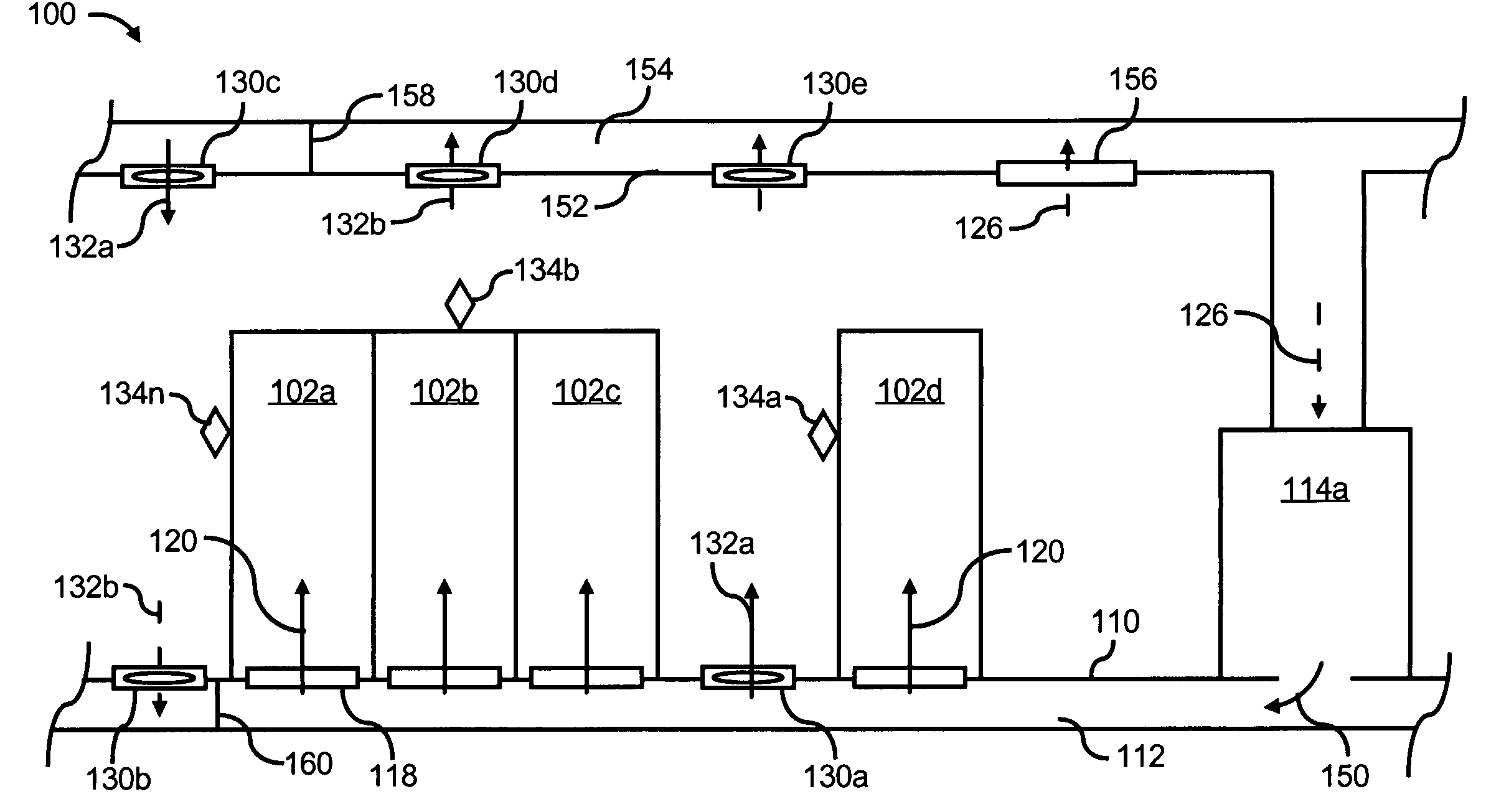
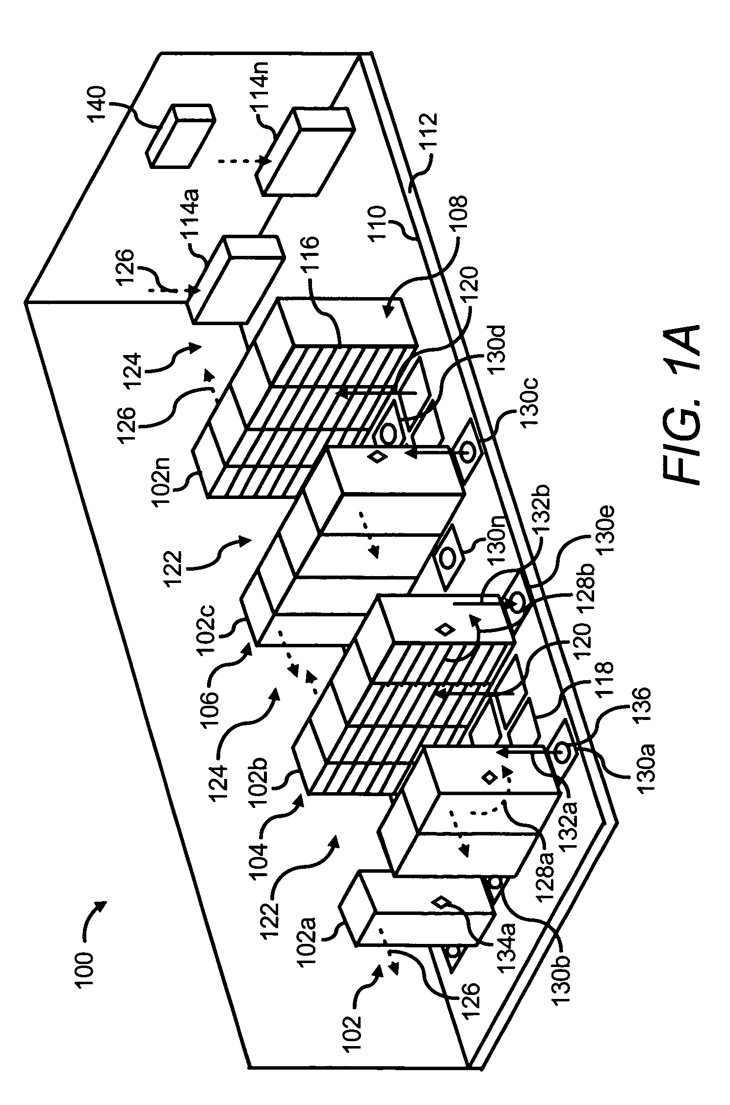
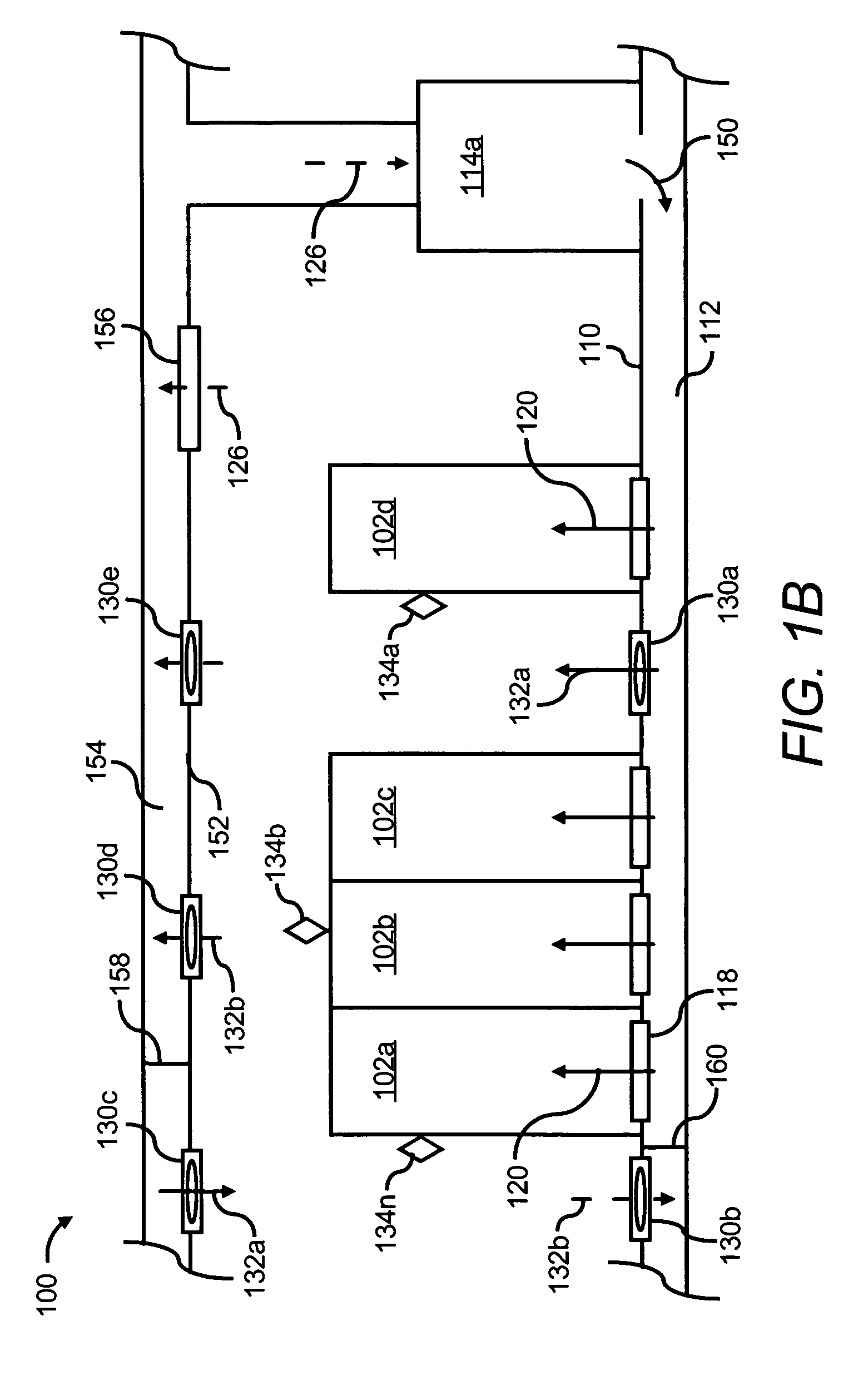
[0013]For simplicity and illustrative purposes, the present invention is described by referring mainly to an exemplary embodiment thereof. In the following description, numerous specific details are set forth in order to provide a thorough understanding of the present invention. It will be apparent however, to one of ordinary skill in the art, that the present invention may be practiced without limitation to these specific details. In other instances, well known methods and structures have not been described in detail so as not to unnecessarily obscure the present invention.

[0014]The adverse effects of air re-circulation in a room containing heat generating devices, such as, hot spot formations, may substantially be reduced through implementation of the systems and methods described herein below. More particularly, secondary vent tiles may be positioned and operated to one or both of change the pressure distribution of re-circulating airflow to thereby divert the airflow and mix coo...


PUM


Abstract

A system for reducing effects of adverse air re-circulation in a room containing at least one heat generating component includes an air conditioning unit configured to cool airflow in the room and at least one cooling vent tile operable to deliver the cooled airflow to the at least one heat generating component. The system also includes at least one secondary vent tile positioned and operated to one of, introduce airflow into a re-circulating airflow and remove airflow from a re-circulating airflow, to thereby respectively divert or vary the temperature of the re-circulating airflow and thereby reduce the effects of air re-circulation in the room.

Description

BACKGROUND[0001]A data center may be defined as a location, for instance, a room that houses computer systems arranged in a number of racks. A standard rack, for instance, an electronics cabinet, is defined as an Electronics Industry Association (EIA) enclosure, 78 in. (2 meters) wide, 24 in. (0.61 meter) wide and 30 in. (0.76 meter) deep. These racks are configured to house a number of computer systems, about forty (40) systems, with future configurations of racks being designed to accommodate 200 or more systems. The computer systems typically dissipate relatively significant amounts of heat during the operation of the respective components. For example, a typical computer system comprising multiple microprocessors may dissipate approximately 250 W of power. Thus, a rack containing forty (40) computer systems of this type may dissipate approximately 10 KW of power.[0002]Data centers are typically equipped with a raised floor with ventilation tiles configured to provide cool air to...

Claims


Application Information

Patent Timeline
Patent Type & Authority Patents(United States)
IPC IPC(8): F25D17/04F24F11/00F25D23/12
CPCH05K7/20745
Inventor BASH, CULLEN E.PATEL, CHANDRAKANT D.SHARMA, RATNESH K.BEITELMAL, ABDLMONEM
Owner HEWLETT-PACKARD ENTERPRISE DEV LP
Why Eureka
Try Eureka