Medical system having a C-arm

a technology of medical system and c-arm, which is applied in the field of medical diagnosis and/or intervention system, to achieve the effects of reducing load torque, reducing movement artifacts, and improving system dynamics

Inactive Publication Date: 2009-09-22
SIEMENS HEALTHCARE GMBH
View PDF5 Cites 7 Cited by
  • Summary
  • Abstract
  • Description
  • Claims
  • Application Information

AI Technical Summary

Benefits of technology

[0006]The object underlying the present invention is to present a medical diagnosis and / or intervention system, which simplifies and scales down the mechanical design of the system adjacent to the detector and in which load torques of the system are reduced.
[0009]The present invention is based on the idea that a change in position of a C-arm by means of a robot with an articulated arm is more effective than an orbital drive of a C-arm in the shape of a segment of a circle. The C-arm can thus be scaled down and load torques reduced, as a result of which the dynamics of the system can be improved, thereby enabling new applications and reducing movement artifacts.

Problems solved by technology

The arrangement of the linear guide 5 between the upper free end of the C-arm and the detector 2 is also cumbersome in an area where collisions with other medical devices in the vicinity of the patient to be examined can easily occur and / or where improved patient accessibility is desirable.

Method used


Image

  • Medical system having a C-arm
  • Medical system having a C-arm

Examples


Embodiment Construction

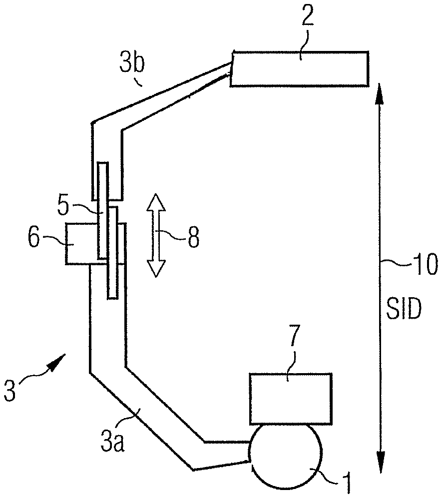
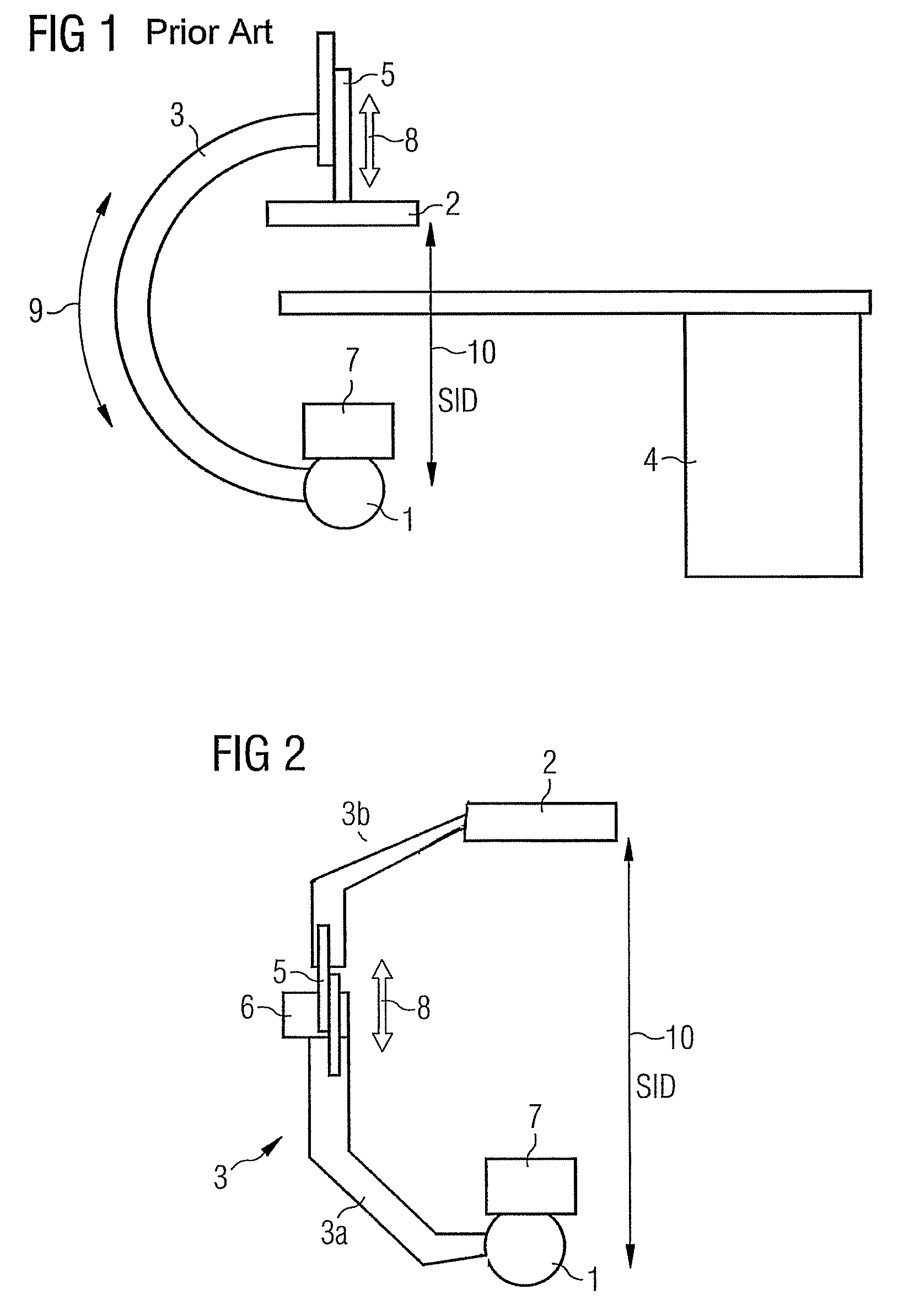
[0013]The design of the system according to the invention essentially differs from a conventional system, as shown in FIG. 1, in that the C-arm is fastened to a free end of an articulated arm (not shown) of a robot by way of a fastening flange 6, and can be moved in three dimensions as a result. This dispenses with the need for the C-arm to be in the shape of a segment of a circle and also allows the linear guide 5 to be repositioned at another location. As shown in FIG. 2, the C-arm 3 of the inventive system consists of a first (lower) part 3a and a second (upper) part 3b. The two parts 3a, 3b of the C-arm 3 are connected with one another by way of a linear guide 5. This is arranged adjacent to the flange point 6 and allows the movement of the upper part 3b specified with the arrow 8. The radiation source detector distance 10 can thus be adjusted. As the linear guide is no longer arranged between the upper free end of the C-arm and the detector, the C-arm can be embodied smaller in...


PUM


Abstract

The present intervention relates to a medical diagnosis or intervention system with a radiation source, a radiation detector, and a C-arm as a component carrier, to which the radiation source and the radiation detector are fastened. The distance between the radiation source and the radiation detector can be changed by means of a linear guide. The C-arm is fastened to an articulated arm of a robot and the linear guide is arranged in the vicinity of the fastening point of the C-arm on the articulated arm.

Description

CROSS REFERENCE TO RELATED APPLICATIONS[0001]This application claims priority of German application No. 10 2007 021 770.8 filed May 9, 2007, which is incorporated by reference herein in its entirety.FIELD OF THE INVENTION[0002]The present invention relates to a medical diagnosis and / or intervention system as claimed in the claims.BACKGROUND OF THE INVENTION[0003]With present-day medical diagnosis and intervention systems, which use a so-called C-arm as a component carrier for the imaging components comprising x-ray generation and adjustment (faceplate and x-ray tube) as well as an x-ray image recording device (e.g. a flat screen detector), the distance between the tube generating radiation and the image converter and / or detector can for the most part be adjusted in order to be able to bring the detector as close as possible to the patient to be examined in order to optimize image quality and / or scattered radiation behavior.[0004]FIG. 1 shows a conventional medical diagnosis and / or i...

Claims


Application Information

Patent Timeline
Patent Type & Authority Patents(United States)
IPC IPC(8): H05G1/02
CPCA61B6/588A61B6/4441
Inventor GREBNER, ALBERTLURZ, WINFRIEDSATTLER, STEFANSCHONBORN, MANFRED
Owner SIEMENS HEALTHCARE GMBH
Why Eureka
Try Eureka