Electrical machine having a segmented stator or rotor

a technology of electric machines and stators, applied in the direction of dynamo-electric machines, magnetic circuit rotating parts, magnetic circuit shapes/forms/construction, etc., can solve the problems of loss and complicated control, high vibration and acoustic noise, and high winding area

Pending Publication Date: 2021-11-18
SIEMENS GAMESA RENEWABLE ENERGY AS
View PDF4 Cites 2 Cited by
  • Summary
  • Abstract
  • Description
  • Claims
  • Application Information

AI Technical Summary

Benefits of technology

[0012]An aspect relates to provide a new segment design, for controlling the shape and dimensions of the circumferential gaps in segmented stators or rotors having half slots at the circumferential ends of the segments, in order to minimize the detrimental effects above described.
[0020]According to embodiments of the present invention, the presence of the circumferential protrusion leads to a reduction in certain cogging and loaded torque harmonics, as well as in the voltage and power harmonics.
[0023]According to embodiments of the invention, the second circumferential width at the respective tooth radial end of the end teeth is the same of the circumferential width at the respective tooth radial end of the intermediate teeth.The width of the radial end of the end teeth is so congruous with all of the other intermediate teeth in the segment. As the top of the coil is no wider than the other teeth in the segment, no special coil design is required for these end teeth, thus maintaining ease of manufacture, and improving the mechanical support for coils at the end of the segment.

Problems solved by technology

Due to manufacturing tolerances and limitations, tolerance circumferential gaps are typically designed between segments.
The presence of the segment circumferential gaps can lead to differences in the electromagnetic performance compared to a single stator and often leads to issues with undesirable torque harmonics and output power harmonics of the electrical machine, which can lead to high levels of vibration and acoustic noise as well as losses and complicated control.
A reduction in winding area would increase the resistance in this particular coil and therefore increase the loss.
By having an imbalance in losses between the coils, a hot spot would be expected to form in the circumferential end coil, thus limiting the operating point of the whole machine from a thermal perspective.
This ensures that the winding area remains identical or similar to all the other slots thus eliminating the risk of hotspots, however, it potentially introduces further torque harmonics and power harmonics due to the resulting uneven distribution of teeth around the airgap circumference.

Method used


Image

  • Electrical machine having a segmented stator or rotor
  • Electrical machine having a segmented stator or rotor
  • Electrical machine having a segmented stator or rotor

Examples


Embodiment Construction

[0030]The illustrations in the drawings are schematic. It is noted that in different figures, similar or identical elements are provided with the same reference signs.

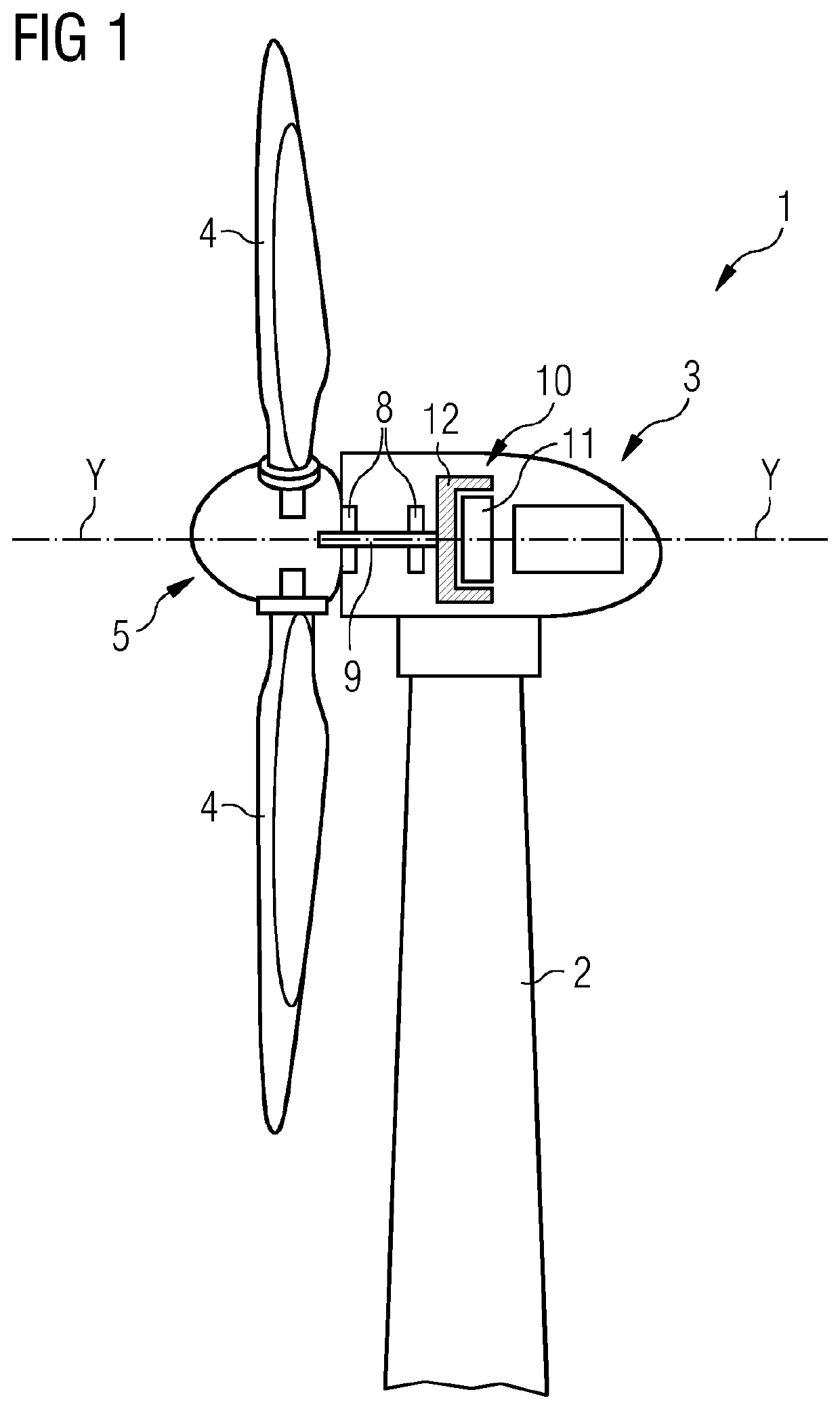
[0031]FIG. 1 shows a wind turbine 1 according to embodiments of the invention. The wind turbine 1 comprises a tower 2, which is mounted on a non-depicted foundation. A nacelle 3 is arranged on top of the tower 2.

[0032]The wind turbine 1 further comprises a wind rotor 5 having two, three or more blades 4 (in the perspective of FIG. 1 only two blades 4 are visible). The wind rotor 5 is rotatable around a rotational axis Y. When not differently specified, the terms axial, radial and circumferential in the following are made with reference to the rotational axis Y. Rotational axis Y may coincide with stator longitudinal axis Y.

The blades 4 extend radially with respect to the rotational axis Y.

The wind turbine 1 comprises a concentrated winding electrical generator 10.

The wind rotor 5 is rotationally coupled with the electr...


PUM


Abstract

Provided is a stator for an electrical machine including a plurality of segments, whereinin order to reduce torque harmonics and power harmonics due to the interposed circumferential gap between two circumferentially adjacent stator segments,at least one of the two end teeth of each stator segment includes a circumferential protrusion at the respective tooth radial end, the circumferential protrusion protruding from the respective side face towards the respective circumferential end.

Description

CROSS-REFERENCE TO RELATED APPLICATIONS[0001]This application claims priority to PCT Application No. PCT / EP2019 / 078411, having a filing date of Oct. 18, 2019, which is based-off of EP Application No. 18203388.6, having a filing date of Oct. 30, 2018, the entire contents both of which are hereby incorporated by reference.FIELD OF TECHNOLOGY[0002]The following relates to an electrical machine having a stator or a rotor with a segmented geometry, i.e., a stator or a rotor including a plurality of stator segments circumferentially joined together.BACKGROUND[0003]In large electrical machines, segmentation of the stator and / or the rotor structure is required to ease manufacturing and transportation. This is in particular required for stators or rotors where a winding is provided. Due to manufacturing tolerances and limitations, tolerance circumferential gaps are typically designed between segments.[0004]The presence of the segment circumferential gaps can lead to differences in the electr...

Claims


Application Information

Patent Timeline
Patent Type & Authority Applications(United States)
IPC IPC(8): H02K1/14H02K1/26H02K1/16H02K3/28
CPCH02K1/148H02K1/265H02K2213/09H02K3/28H02K2213/12H02K1/165
Inventor AZAR, ZIADCLARK, RICHARDDUKE, ALEXANDERTHOMAS, ARWYN
Owner SIEMENS GAMESA RENEWABLE ENERGY AS
Why Eureka
Try Eureka