Variable speed drive system and method for starting and/or operating a variable speed drive system

Inactive Publication Date: 2018-05-17
VOITH PATENT GMBH
View PDF15 Cites 3 Cited by
  • Summary
  • Abstract
  • Description
  • Claims
  • Application Information

AI Technical Summary

Benefits of technology

[0007]Against the background of this problem, it is an object of the present invention to provide a variable-speed drive system of the type mentioned at the outset in which the wear occurring in the main transmission is kept as small as possible, that the speed-controllable drive or the differential drive can be controlled during the start-up of the ma

Problems solved by technology

A disadvantage of the solutions known from WO 2014/169302 A1 and WO 2011/000008 A1 is in particular the wear of the main transmission, which couples the drive to the output, wherein this wear is caused by the engagement of the speed-controllable drive or differential drive.
It is further disadvantageous that during st

Method used


Image

  • Variable speed drive system and method for starting and/or operating a variable speed drive system
  • Variable speed drive system and method for starting and/or operating a variable speed drive system
  • Variable speed drive system and method for starting and/or operating a variable speed drive system

Examples


Embodiment Construction

[0040]Only those elements which are essential for the direct understanding of the invention are shown.

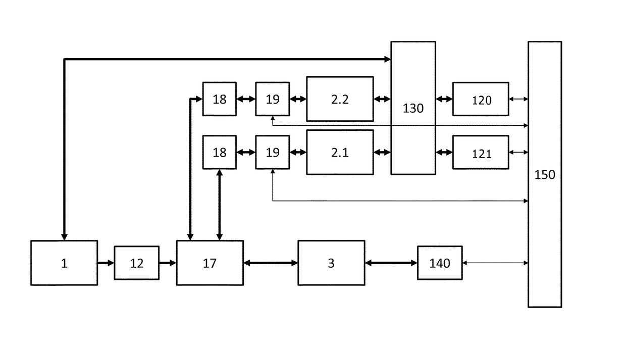
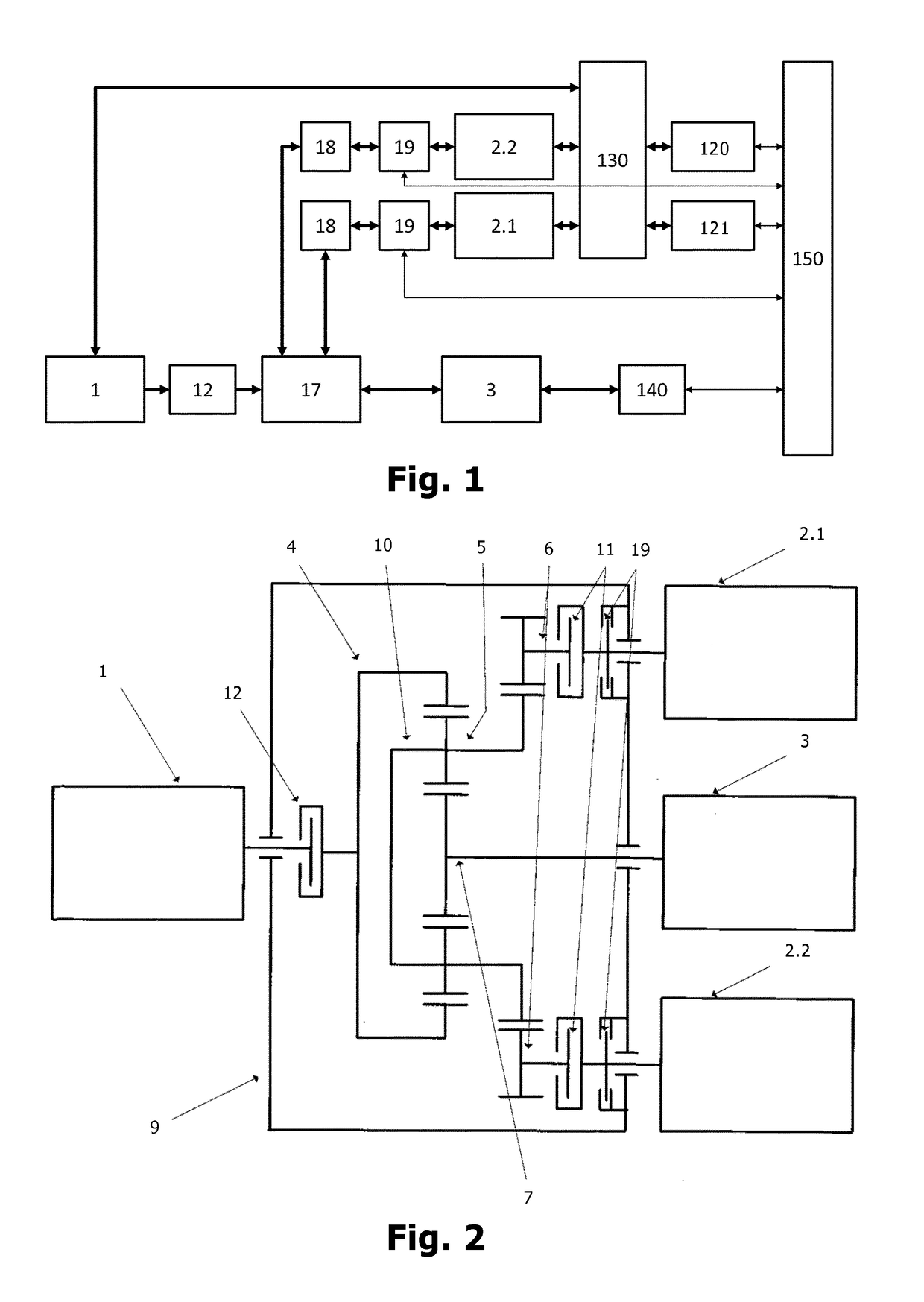
[0041]The schematic illustration of a variable-speed drive system indicated in FIG. 1 shows a transmission unit 17 with a central input shaft on a drive machine 1, such as an electric induction machine, and with a central output shaft on a driven machine 3.

[0042]The transmission unit 17 is preferably designed as a planetary gear which has a sun gear 7, a planet carrier 10 with planetary gears 5 (also referred to as “planets” in the following) and a ring gear 4. Thus, coaxiality between the input (drive) and output (driven) shaft is realized.

[0043]Two regulating machines 2.1, 2.2 are coupled to the transmission unit 17 via respective transmission stages 18 of a branch, and can thus feed power into the drive machine 1. The two regulating machines 2.1, 2.2 may be independent speed-controllable electric motors.

[0044]The connection of the input and output shaft to the planetary gear can ...


PUM


Abstract

A variable-speed drive system includes a driven machine mechanically coupled to a drive machine by a transmission unit. At least two regulating machines are mechanically coupled to the transmission unit and operated by at least two frequency converters. At least one of the at least two frequency converters is electrically connected to the drive machine by a changeover device, wherein a connection of the drive machine to at least one electric supply network is at least temporarily disconnectable to produce a controlled speed change on the drive machine.

Description

CROSS-REFERENCE TO RELATED PATENT APPLICATIONS[0001]This patent application is a United States national phase patent application based on PCT / EP2016 / 059387 filed Apr. 27, 2016, which claims the benefit of German Patent Application No. DE 10 2015 107 934.8 filed May 20, 2015, the entire disclosures of which are hereby incorporated herein by reference.FIELD[0002]The present invention relates to a variable-speed drive system.BACKGROUND[0003]Variable speed drive systems are used in the industrial application in order to better adapt the power to be transferred to the respective process requirements. They are implemented in a variable-speed configuration especially in drive systems of compressors in the oil and gas industry, but also in fans of high power and in the drive of pumps in thermal power plants.[0004]For example, a drive system is known from printed publication WO 2014 / 169302 A1, which has a speed-constant electric main drive, a rotor further as an output, a main transmission, ...

Claims


Application Information

Patent Timeline
IPC IPC(8): H02P1/46H02P5/753
CPCH02P1/46H02P5/753H02P9/06
Inventor LAUTER, BERNDLINDENMAIER, JOCHEN
Owner VOITH PATENT GMBH
Why Eureka
Try Eureka