Method and device for producing a borehole in the soil

Inactive Publication Date: 2009-06-16
BAUER MASCH GMBH
View PDF13 Cites 18 Cited by
  • Summary
  • Abstract
  • Description
  • Claims
  • Application Information

AI Technical Summary

Benefits of technology

[0033]An especially high quality of the foundation member and/or wall member developing during the filling of the borehole can be attained in that a closing device is provided for closing the outlet opening. The closing device is preferably designed such that the outlet opening can be closed by placing the core pipe onto the bottom of the borehole. The closing device can include e.g. a piston arranged in an axially movable manner inside the core pipe, which is formed at its front face with a contact surface for outcropping soil. During drilling this piston is suitably pushed by outcropping soil material into the core pipe, whereby an outlet opening arranged laterally on the core pipe can be closed. However, when the conveyor screw is retracted the piston can move axially out of the core pipe due to the effect of pressure or gravity or by means of a resetting device and therefore make the outlet opening free. Instead of a piston arranged inside the core pipe the closing device can also have a sleeve that is movable axially on the outside of the co

Problems solved by technology

However, this configuration does not prove to be ideal for all operating conditions.
In turn, the low rotational speed can perhaps be too low for a speedy conveying away of the material.
In particular, coarse granules can repeatedly slide

Method used


Image

  • Method and device for producing a borehole in the soil
  • Method and device for producing a borehole in the soil
  • Method and device for producing a borehole in the soil

Examples


Example

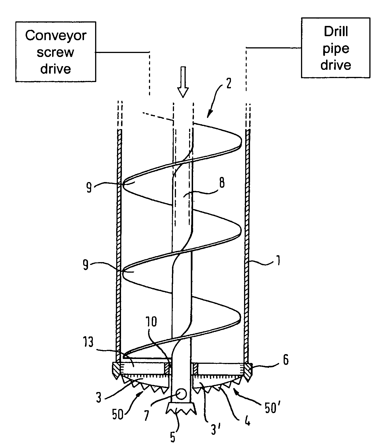
[0045]A first embodiment of a device according to the invention for producing a borehole in the soil is shown in FIGS. 1 and 2. The device includes a rotatably driven drill pipe 1, in which a conveyor screw 2 is arranged coaxially. The conveyor screw 2 has a core pipe 8, on the outside of which a helical flight 9 extends longitudinally.

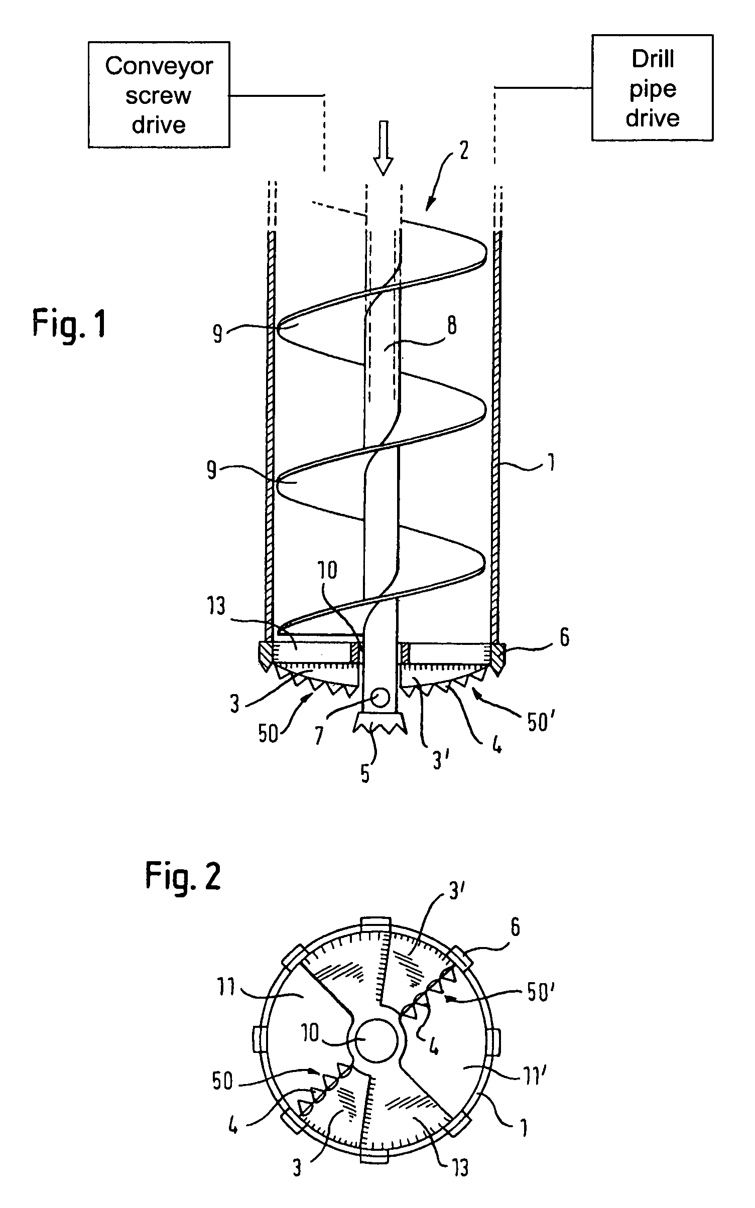
[0046]At the end of the drill pipe 1 that faces towards the borehole a tool holder 13 designed as a cover plate is provided that covers the drill pipe 1 to some extent. The tool holder 13 extends in sections from the wall of the drill pipe 1 in the radial direction towards the longitudinal axis of the drill pipe 1. In the tool holder 13, two openings 11, 11′ in the shape of a circular sector are formed that permit a transport of material through the tool holder 13 towards the inside of the drill pipe and towards the conveying portion of the conveyor screw 2.

[0047]Lying diametrically opposite with respect to the longitudinal axis of the drill pipe 1, t...


PUM


Abstract

The invention relates to a method for producing a borehole in the soil, in which a drill pipe and a conveyor screw arranged inside the drill pipe are set into rotation and introduced into the soil, and in which outcropping soil material is loosened by means of at least one main cutting edge, which is positioned axially in front of the conveyor screw, and is conveyed by means of the conveyor screw in the inside of the drill pipe. In accordance with the invention provision is made for the main cutting edge to be arranged on the drill pipe and to be rotated therewith. The invention further relates to a device for producing a borehole in the soil which can be employed in the method according to the invention.

Description

BACKGROUND OF THE INVENTION[0001]1. Field of the Invention[0002]The invention relates to a method for producing a borehole in the soil. In such a method provision is made in that a drill pipe and a conveyor screw arranged inside the drill pipe are set into rotation and introduced into the soil and in that outcropping soil material is loosened by means of at least one main cutting edge, which is positioned axially in front of the conveyor screw, and is conveyed away by means of the conveyor screw in the inside of the drill pipe.[0003]The invention further relates to a device for producing a borehole in the soil, comprising a drill pipe, a conveyor screw arranged inside the drill pipe and at least one main cutting edge which is positioned axially in front of the conveyor screw for stripping soil material.[0004]The boreholes may serve to produce foundation members and / or pile walls in particular.[0005]2. Related Art[0006]Methods and devices for cased soil drilling, in particular twin-h...

Claims


Application Information

Patent Timeline
IPC IPC(8): E21B10/44
CPCE21B7/005E21B10/44
Inventor SCHWAB, GEROLD
Owner BAUER MASCH GMBH
Why Eureka
Try Eureka