Dual drive radiator fan and coolant pump system for an internal combustion engine

a technology of radiator fans and cooling pumps, which is applied in the direction of engine cooling devices, machines/engines, mechanical devices, etc., to achieve the effect of reducing parasitic losses and low weight and mass

Inactive Publication Date: 2009-10-06
FORD GLOBAL TECH LLC
View PDF15 Cites 9 Cited by
  • Summary
  • Abstract
  • Description
  • Claims
  • Application Information

AI Technical Summary

Benefits of technology

[0010]It is an advantage of a dual drive radiator fan and coolant pump system according to the present invention that the packaging of the fan drive and water pump or coolant pump drive is very compact and low in weight and mass.
[0011]It is another advantage of a dual drive radiator fan and coolant pump system according to the present invention that parasitic losses are reduced because the fan hub is journaled upon the coolant pump's impeller shaft, which is always rotating when the engine is in operation.
[0012]It is yet another advantage of a dual drive radiator fan and coolant pump system according to the present invention that failure of one of the drive belts may be compensated for through the use of an overrunning clutch between the fan hub and the impeller shaft.
[0013]It is yet another advantage of a dual drive radiator fan and coolant pump system according to the present invention that excessive fan noise may be abated because the fan may be turned at a lower speed, while nevertheless maintaining the water pump speed at a higher value.

Problems solved by technology

If an overrunning clutch is employed, failure of one of the drive belts may occasion the use of the single surviving drive belt to power not only the fan hub, but also the coolant pump.

Method used


Image

  • Dual drive radiator fan and coolant pump system for an internal combustion engine
  • Dual drive radiator fan and coolant pump system for an internal combustion engine
  • Dual drive radiator fan and coolant pump system for an internal combustion engine

Examples


Embodiment Construction

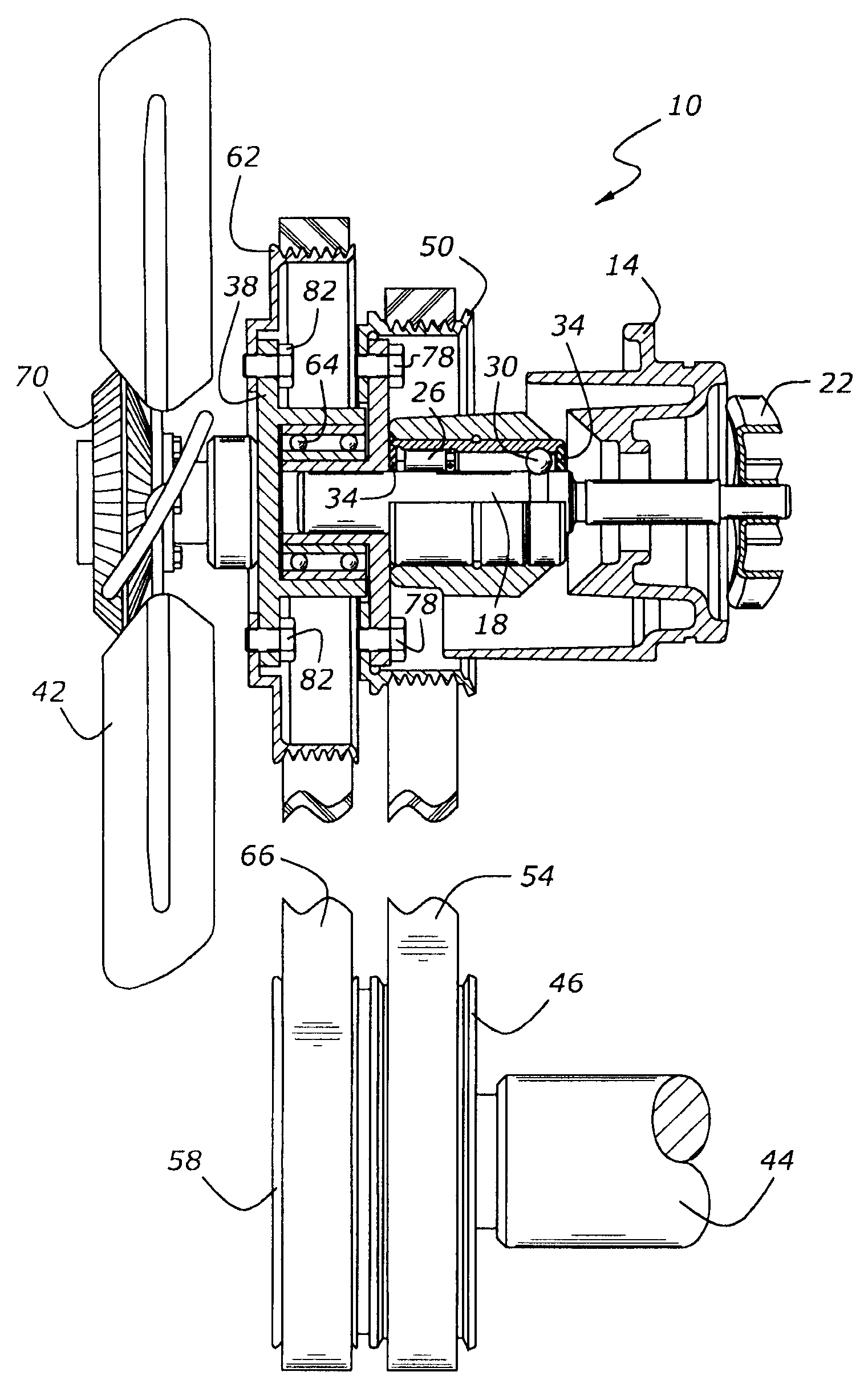
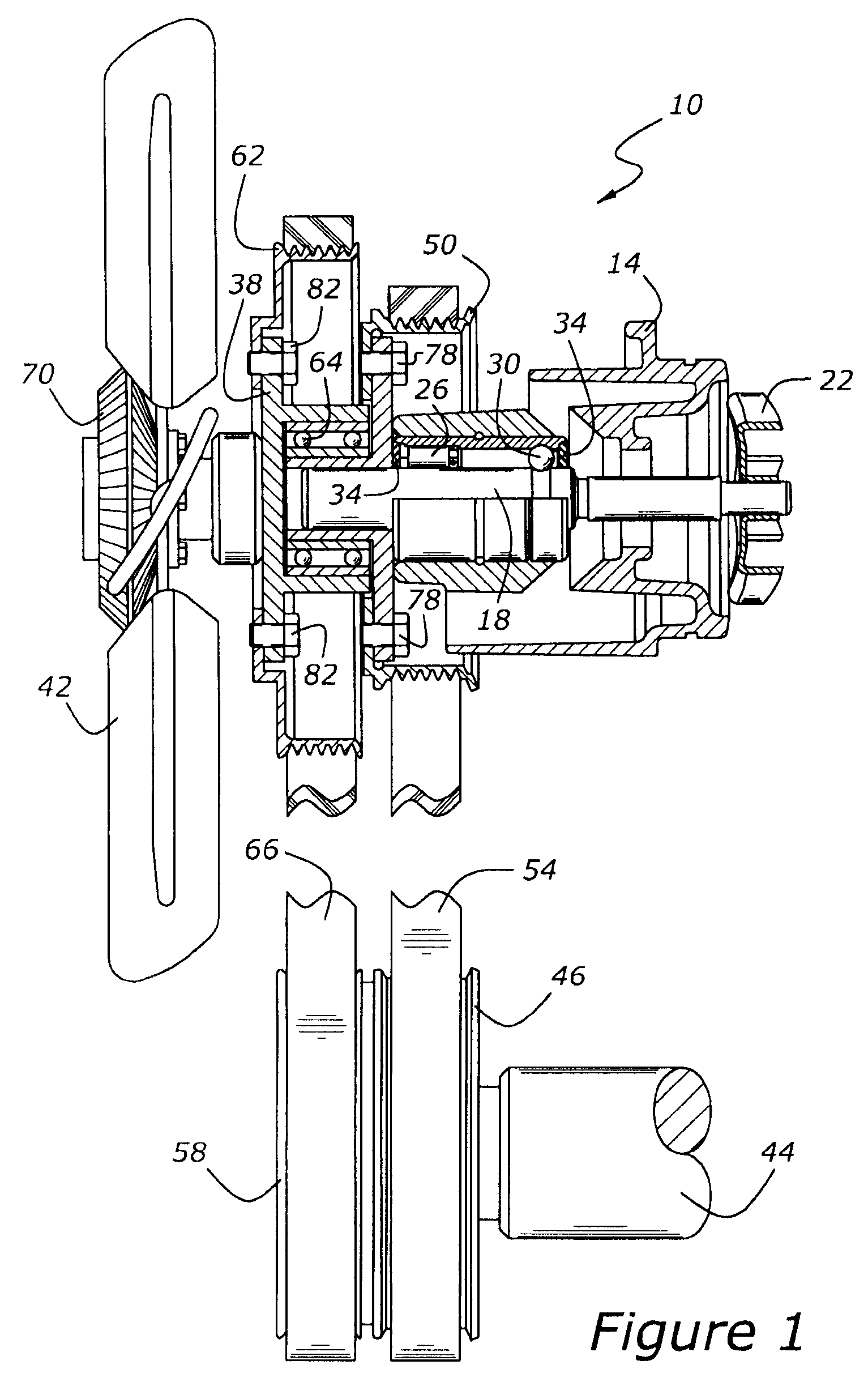
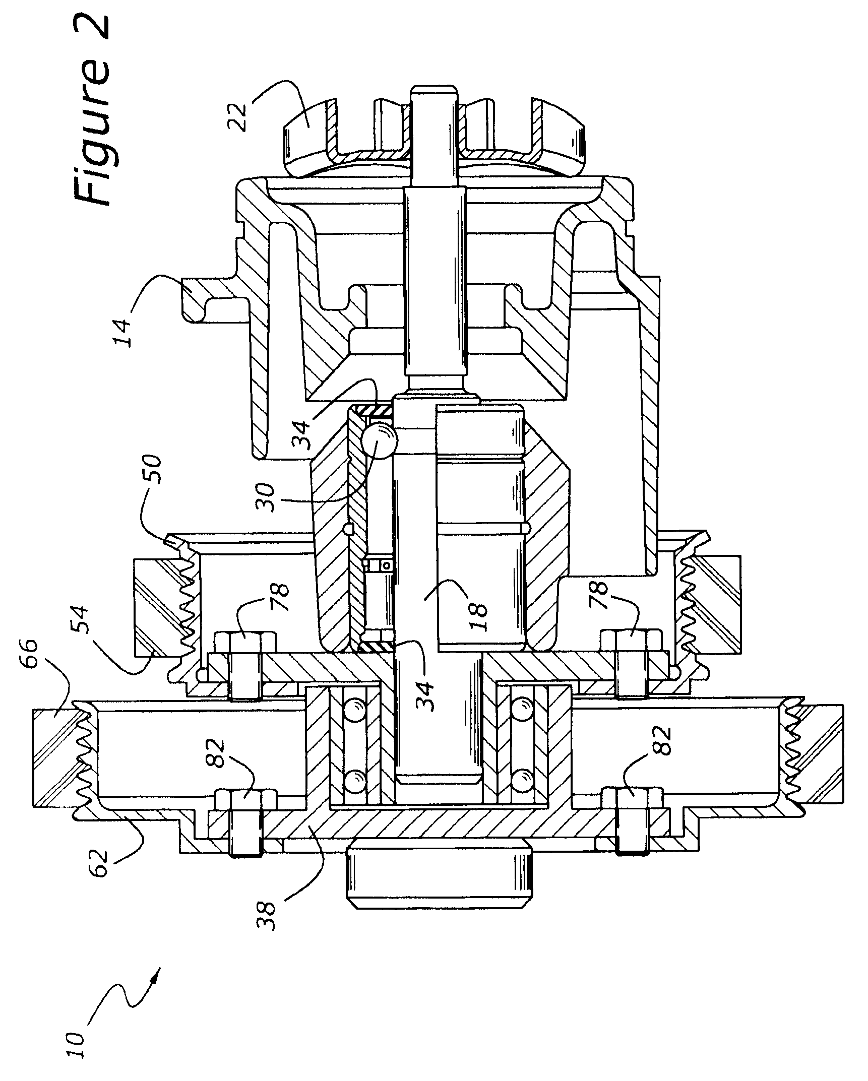
[0018]As shown in FIGS. 1 and 2, a dual drive radiator fan and coolant pump system, 10, includes a coolant pump, 14, having an impeller, 22, mounted upon an impeller shaft, 18, which is driven by the engine's crankshaft, 44. Pump drive flange 52 is fit upon a forward portion of impeller shaft 18. Pump drive flange 52 is driven by pump pulley 50, which is powered by first composite drive belt 54, which is connected with a first driving pulley, 46, which, in turn is rotationally locked to crankshaft 44. Drive flange 52 and pump pulley 50 are connected by several fasteners 78.

[0019]Pump drive flange 52 has a cylindrical extension 52A upon which a double row ball type of fan bearing 64 is mounted. Bearing 64, although illustrated as a double row ball bearing, is merely illustrative of a class of anti-friction bearings suitable for mounting fan hub 38 upon pump drive flange 52.

[0020]Although fan hub 38 is mounted upon coolant pump drive flange 52, fan bearing 64 causes fan hub 38 to be u...


PUM


Abstract

A dual drive radiator fan and coolant pump system for a liquid-cooled reciprocating internal combustion engine includes a coolant pump with an impeller shaft driven by a first drive extending between the engine's crankshaft and a pump pulley and hub mounted upon the impeller shaft. A second drive extends between the crankshaft and a fan hub journaled upon the pump hub, so that the coolant pump and fan hub are driven independently.

Description

CROSS REFERENCE TO RELATED APPLICATIONS[0001]None.BACKGROUND OF THE INVENTION[0002]1. Field of the Invention[0003]The subject matter disclosed herein relates to coolant pump and radiator fan drive for use with a reciprocating liquid-cooled internal combustion engine.[0004]2. Related Art[0005]Liquid-cooled reciprocating internal combustion engines typically employ a coolant pump (commonly termed a “water pump”), to circulate coolant between a heat exchanger, commonly termed a “radiator,” and the engine. The radiator is an air-to-liquid heat exchanger which usually has a fan to pull ambient air through the radiator core. On heavy duty vehicles, the fan is usually powered by the engine's crankshaft. With most engines, the fan and a pump impeller are mounted on a single shaft extending through the coolant pump to a fan clutch. Unfortunately, with this arrangement it is not possible to drive the fan at a speed which is different from the water pump speed except by the use of a fan clutch...

Claims


Application Information

Patent Timeline
Patent Type & Authority Patents(United States)
IPC IPC(8): F01P7/02F01P5/10
CPCF01P5/04F02B67/06F01P5/12
Inventor KROLEWSKI, DAVID R.DRAWE, MIKE W.DRAWE, LEGAL REPRESENTATIVE, KATHLEEN K.
Owner FORD GLOBAL TECH LLC
Why Eureka
Try Eureka