Handle thumb wheel mechanism which maintains holding forces when sterilized and when engaged

a thumb wheel and holding force technology, applied in the field of thumb wheel mechanism, can solve problems such as the decrease of holding for

Inactive Publication Date: 2009-10-20
BOSTON SCI SCIMED INC
View PDF19 Cites 24 Cited by
  • Summary
  • Abstract
  • Description
  • Claims
  • Application Information

AI Technical Summary

Benefits of technology

[0004]The thumb wheel mechanism is exposed to elevated temperatures when it is in neutral position during sterilization. By reducing the stress on the mechanism while in neutral position, this invention minimizes the amount of stress to the thumb wheel mechanism while it is exposed to an elevated temperature during sterilization. This is accomplished by applying a minimal compression load to the thumb wheel mechanism in neutral position.

Problems solved by technology

When the materials are exposed to an elevated temperature, they experience a decrease in modulus, causing the materials to yield within the assembly resulting in a decrease in holding force.

Method used


Image

  • Handle thumb wheel mechanism which maintains holding forces when sterilized and when engaged
  • Handle thumb wheel mechanism which maintains holding forces when sterilized and when engaged
  • Handle thumb wheel mechanism which maintains holding forces when sterilized and when engaged

Examples


Embodiment Construction

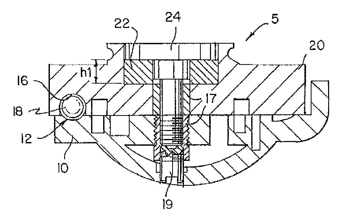
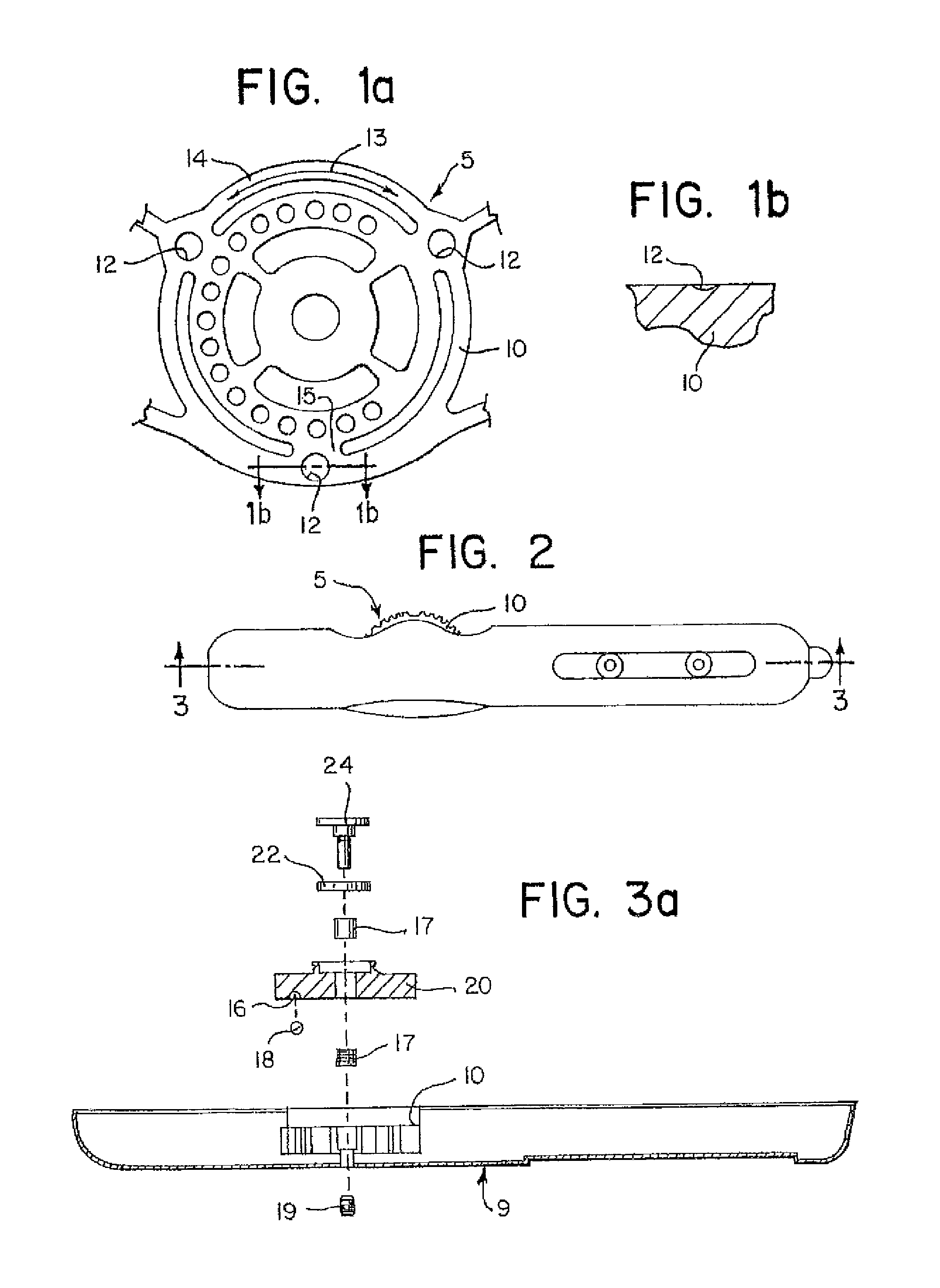
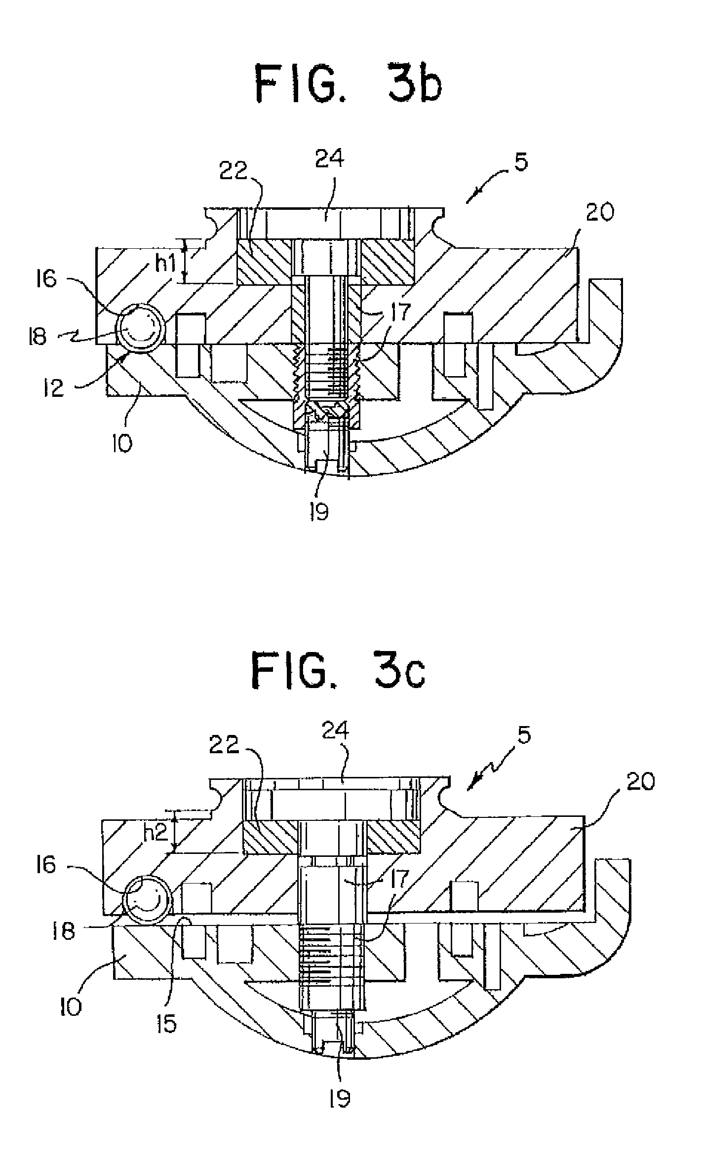
[0019]As shown in FIGS. 1a, 1b, 3a, 3b and 3c, one embodiment of the invention consists of thumb wheel mechanism 5 as follows: a handle half bolt circle 10 with three equally spaced full radius divots 12. Three equally spaced counter bores 16 on a thumb wheel 20 (as shown in FIG. 3a) to the handle half 10 are positioned on the thumb wheel 20. Three stainless steel balls 18 are pressed into each of the three counter bores 16 in the thumb wheel 20. The balls 18 can also be constructed from plastic, such as a polymer, nylon, Delrin® (manufactured by Hi-Tech Profiles, Inc., Pawcatuck, Conn.) and ABS® (manufactured by Hi-Tech Profiles, Inc., Pawcatuck, Conn.). The balls 18 either are nested into the base of the divots 12 or ride just outside the divots 12 on a level surface 15 of the handle half 10 along an arcuate path indicated as 13 in FIG. 1a. A friction disk 22 is inserted under the head of a shoulder screw 24. The shoulder screw 24 and passes through the thumb wheel 20 acting as an...


PUM


Abstract

A thumb wheel mechanism includes a thumb wheel with upper and lower surfaces, the lower surface including a bore with a ball connected to it, and an handle half with upper and lower surfaces, the upper surface including a divot, the thumb wheel lower surface being aligned with the handle half upper surface so that the ball rests in the divot of the handle half upper surface when the thumb wheel mechanism is in the neutral position, thereby minimizing the compression load on the thumb wheel mechanism.

Description

FIELD OF THE INVENTION[0001]This invention relates to a thumb wheel mechanism for a deflectable tip catheter. More particularly, this invention relates to a thumb wheel mechanism with a minimized compression force in a neutral position and a locking frictional force in an engaged position.BACKGROUND OF THE INVENTION[0002]A two dimensional / three dimensional steerable catheter can deflect four pull cables, generating curves in four different planes. Currently, this is accomplished by having a distal tip segment that can be deflected into four independent quadrants using separate pull cables attached to a distal tip. The four pull cables are controlled by two independent mechanisms. One of the mechanisms consists of a thumb wheel that, when rotated both in a clockwise and a counterclockwise direction from a neutral position, generates tension to two of the four independent cables. The second mechanism utilizes a slider control, which when slid forward and backward from a neutral positi...

Claims


Application Information

Patent Timeline
Patent Type & Authority Patents(United States)
IPC IPC(8): A61M37/00A61M31/00A61B1/00A61B18/18A61M25/00A61B18/14A61M25/01
CPCA61B18/1492A61M25/0136A61B18/1815A61B2018/1435A61B2018/00839
Inventor FALWELL, GARY S.BURNS, STEVEN J.
Owner BOSTON SCI SCIMED INC
Why Eureka
Try Eureka