Electric power steering apparatus

a technology of electric steering and electric motor, which is applied in the direction of electrical steering, vehicle components, gearing, etc., can solve the problems of vibration and noise, and achieve the effect of reducing vibration and nois

Active Publication Date: 2007-10-09
JTEKT CORP +1
View PDF23 Cites 24 Cited by
  • Summary
  • Abstract
  • Description
  • Claims
  • Application Information

AI Technical Summary

Benefits of technology

[0010]In the present mode, the movement in the mesh of the teeth of the belt and the teeth of each of

Problems solved by technology

However, there is a case where vibration and noise are produced by the mesh of the teeth of the belt and the teeth of each of

Method used


Image

  • Electric power steering apparatus
  • Electric power steering apparatus
  • Electric power steering apparatus

Examples


Embodiment Construction

[0019]A preferred embodiment of the present invention will be described while referring to the drawings.

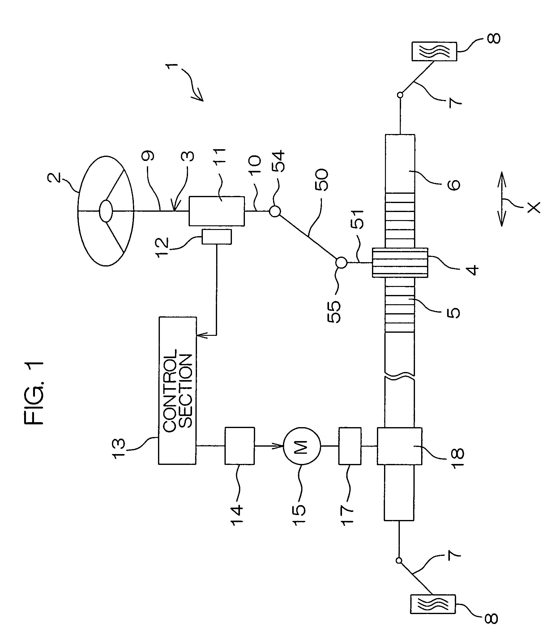
[0020]FIG. 1 is a schematic view showing the schematic configuration of an electric power steering apparatus according to a first embodiment of the present invention. Referring to FIG. 1, an electric power steering apparatus (EPS) 1 comprises a steering shaft 3 connected to a steering wheel 2 serving as a steering member, an intermediate shaft 50 connected to the steering shaft 3 through a universal joint 54, a pinion shaft 51 serving as a steering shaft connected to the intermediate shaft 50 through a universal joint 55, and a rack shaft 6 serving as a steering shaft having a rack 5 meshed with a pinion 4 provided at a front end of the pinion shaft 51 and extending along a width X of a vehicle.

[0021]Tie rods 7 are respectively coupled to both ends of the rack shaft 6, and each of the tie rods 7 is connected to a corresponding wheel 8 through a corresponding knuckle arm (not shown...


PUM


Abstract

An electric power steering apparatus comprises an electric motor for producing a steering assist force, and a speed reduction mechanism for decelerating the rotation of an output shaft in the electric motor. The speed reduction mechanism comprises an input pulley driven by the electric motor, an output pulley connected to a steering shaft, and a belt for connecting the input pulley and the output pulley to each other. The belt comprises a helical toothed belt. The input pulley and the output pulley respectively include helical toothed pulleys meshed with the helical toothed belt.

Description

BACKGROUND OF THE INVENTION[0001]1. Field of the Invention[0002]The present invention relates to an electric power steering apparatus that produces a steering assist force by an electric motor.[0003]2. Description of Related Art[0004]In a rack assist type electric power steering apparatus that provides a steering assist force through a rack shaft, the rotation of an output shaft in an electric motor is decelerated through a speed reduction mechanism composed of a pulley belt mechanism. The output rotation of the speed reduction mechanism is converted into the axial movement of a rack shaft through a ball screw mechanism, for example, surrounding the rack shaft (see Japanese Unexamined Patent Publication No. 62-4673 (1987), for example).[0005]An advantage of this case is that a belt is interposed in a power transmission path between the electric motor and the rack shaft, so that shock loading and vibration from the rack shaft are not transmitted to the electric motor.[0006]In order t...

Claims


Application Information

Patent Timeline
IPC IPC(8): F16H35/00B62D5/04F16H7/02
CPCB62D5/0412F16H7/023B62D5/0424
Inventor SARUWATARI, TAKEHIROMURAKAMI, TETSUYAMURATAKA, HIROSHIHIRONAKA, AKIHIRO
Owner JTEKT CORP
Why Eureka
Try Eureka