Vacuum cleaner

a vacuum cleaner and vacuum technology, applied in the field of vacuum cleaners, to achieve the effect of strong compressing force of the compressing par

Inactive Publication Date: 2010-01-05
SAMSUNG GWANGJU ELECTRONICS CO LTD
View PDF13 Cites 42 Cited by
  • Summary
  • Abstract
  • Description
  • Claims
  • Application Information

AI Technical Summary

Benefits of technology

[0010]The present disclosure provides a vacuum cleaner which requires small space for installation of a structure for compressing dust collected in a dust collecting part, and which provides strong compressing force of the compressing part.

Problems solved by technology

Also, the present disclosure is not required to overcome the disadvantages described above, and an exemplary embodiment of the present disclosure may not overcome any of the problems described above.

Method used


Image

  • Vacuum cleaner
  • Vacuum cleaner
  • Vacuum cleaner

Examples


Embodiment Construction

[0034]Certain exemplary embodiments of the present disclosure will now be described in greater detail with reference to the accompanying drawings. In the following description, same drawing reference numerals are used for the same elements even in different drawings. The matters defined in the description, such as detailed construction and elements, are provided to assist in a comprehensive understanding of the disclosure. Thus, it is apparent that the present disclosure can be carried out without those specifically defined matters. Also, well-known functions or constructions are not described in detail since they would obscure the disclosure with unnecessary detail.

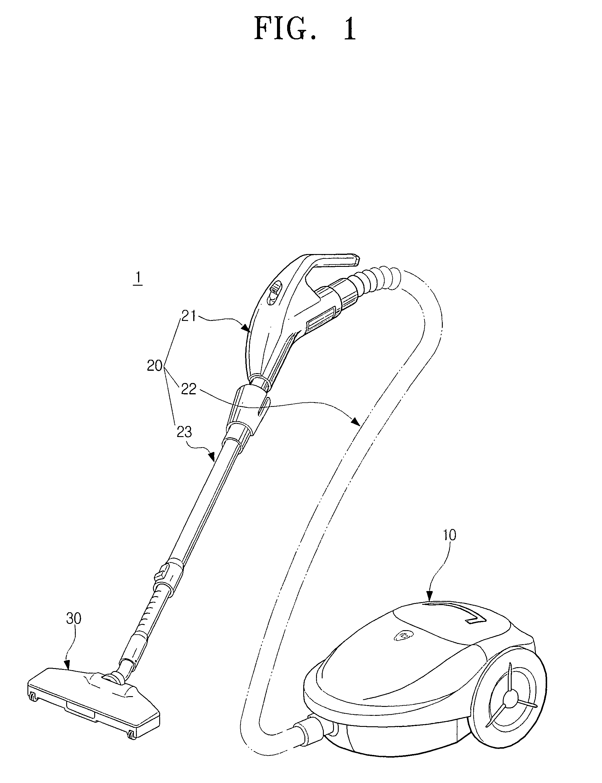
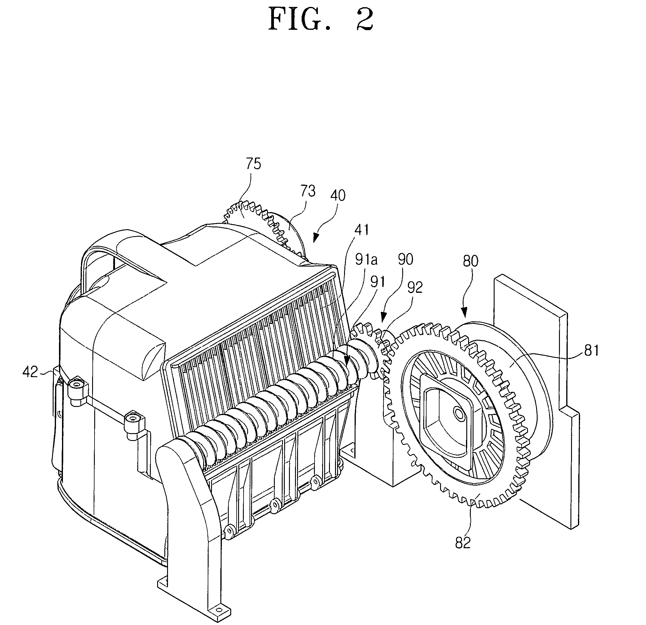
[0035]FIG. 1 is a perspective view of a vacuum cleaner according to an exemplary embodiment of the present disclosure, FIG. 2 is a perspective view of a cyclone dust separating unit, an electric wire winding unit, and a filter cleaning unit, all of which being housed in a main cleaner body of FIG. 1, FIG. 3 is a perspect...


PUM


Abstract

A vacuum cleaner includes a cyclone dust separating unit which includes a cyclone part to separate dust from a dust-laden air drawn from a surface being cleaned using a centrifugal force, a dust collecting part comprising a dust chamber to accommodate the dust separated at the cyclone part, and a compressing part to compress the dust accommodated in the dust chamber. The compressing part includes a driving part to rotatably drive a driving axis, and a compressing plate driven in a substantially perpendicular direction with respect to the driving axis according to the rotation of the driving axis, and to compress the dust accommodated in the dust chamber. As a result, a vacuum cleaner is provided, which requires a minimum space for the installation of a compressing part to compress dust inside the dust collecting part, and provides maximum compressing force of the compressing part.

Description

CROSS-REFERENCE TO RELATED APPLICATIONS[0001]This application claims priority from U.S. Provisional Application No. 60 / 926,832, filed Apr. 30, 2007, with the United States Patent and Trademark Office, and Korean Patent Application No. 10-2007-0059485, filed on Jun. 18, 2007, in the Korean Intellectual Property Office, the disclosure of which is incorporated herein by reference in its entirety.BACKGROUND OF THE INVENTION[0002]1. Field of the Invention[0003]The present disclosure relates to a vacuum cleaner, and more particularly, to a vacuum cleaner which requires a minimum space for the installation of a compressing part to compress dust collected in a dust receptacle, and which provides maximum compressing force.[0004]2. Description of the Related Art[0005]A vacuum cleaner generally cleans a surface using a suction force.[0006]In such a general vacuum cleaner, air containing dust is drawn into the vacuum cleaner, and dust is separated from the drawn-in air and stored in a predefine...

Claims


Application Information

Patent Timeline
Patent Type & Authority Patents(United States)
IPC IPC(8): A47L9/20A47L5/34
CPCA47L9/108A47L9/26A47L9/20A47L9/1666
Inventor OH, JANG-KEUNLEE, JIN-GONCHA, SEUNG-YONG
Owner SAMSUNG GWANGJU ELECTRONICS CO LTD
Why Eureka
Try Eureka