Sealed housing and method of producing the same

Active Publication Date: 2014-10-30
WACKER NEUSON SE
View PDF1 Cites 4 Cited by
  • Summary
  • Abstract
  • Description
  • Claims
  • Application Information

AI Technical Summary

Benefits of technology

The present invention aims to provide a housing that can be easily and economically produced and can be opened non-destructively for revision and repair purposes. The invention also aims to provide a sealed housing for a water heater in a motor vehicle, which is simple and reliable to seal. The invention suggests a method for sealing the housing using an elongate positive locking element that can be easily inserted and removed. The housing is designed to be sealed without the need for tightening screws, and the sealing effect is achieved through a form fit connection between the housing parts. The invention also includes a design for the elongate positive locking element that allows for easy and reliable sealing of the housing.

Problems solved by technology

These devices are especially electronic control devices, which may be sensitive to contamination and environmental influences as well as humid air.
Screw connections are additionally disadvantageous insofar as they may become loose due to the vibrations in the vehicle.
The desired leakproofness of the sealed housing will thus get lost.
In the case of a water heater, the medium conducted in the heating circuit may escape through the leak, and this may result in excessively high temperatures in the system and cause substantial damage to the system in its entirety.
It is indeed possible to join the housing cover and the housing lower part by welding or by an adhesive, but this kind of connection between the two housing parts prevents easy opening of the housing for the purpose of revision or repair.
Producing the housing of identical substances is thus not always possible.
Especially in media-carrying housings, substantial tensions may occur on the joining area due to the operating pressure of the respective medium, and a welded joint, in particular a welded joint of plastic materials, will not always be able to reliably resist these tensions.
Hence, a welded joint between the housing parts to be joined entails the risk that the housing will fail when subjected to an internal pressure of the medium accommodated and sealed in the sealed housing.

Method used


Image

  • Sealed housing and method of producing the same
  • Sealed housing and method of producing the same
  • Sealed housing and method of producing the same

Examples


Embodiment Construction

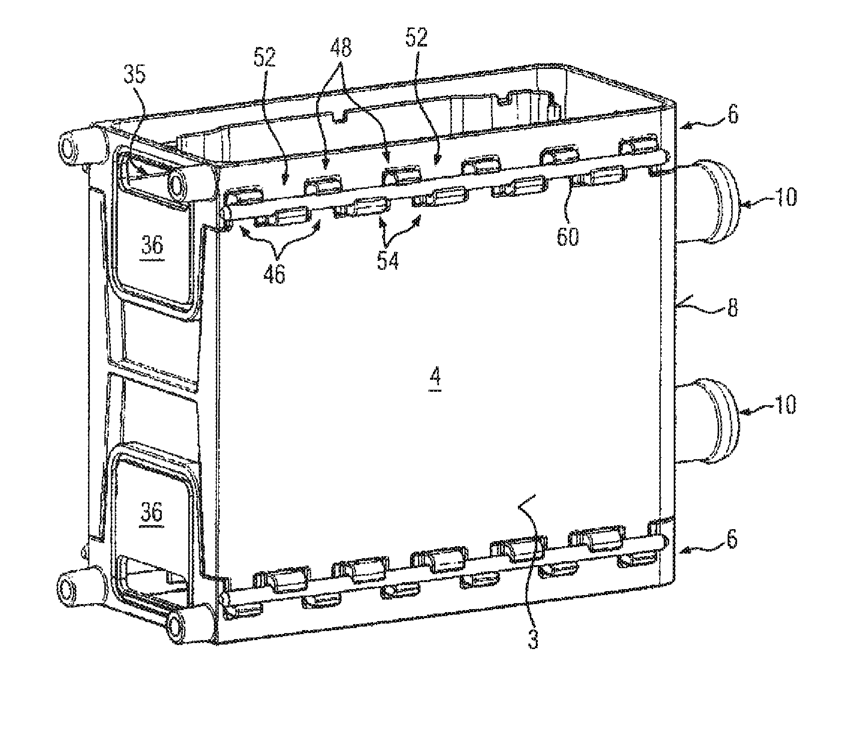
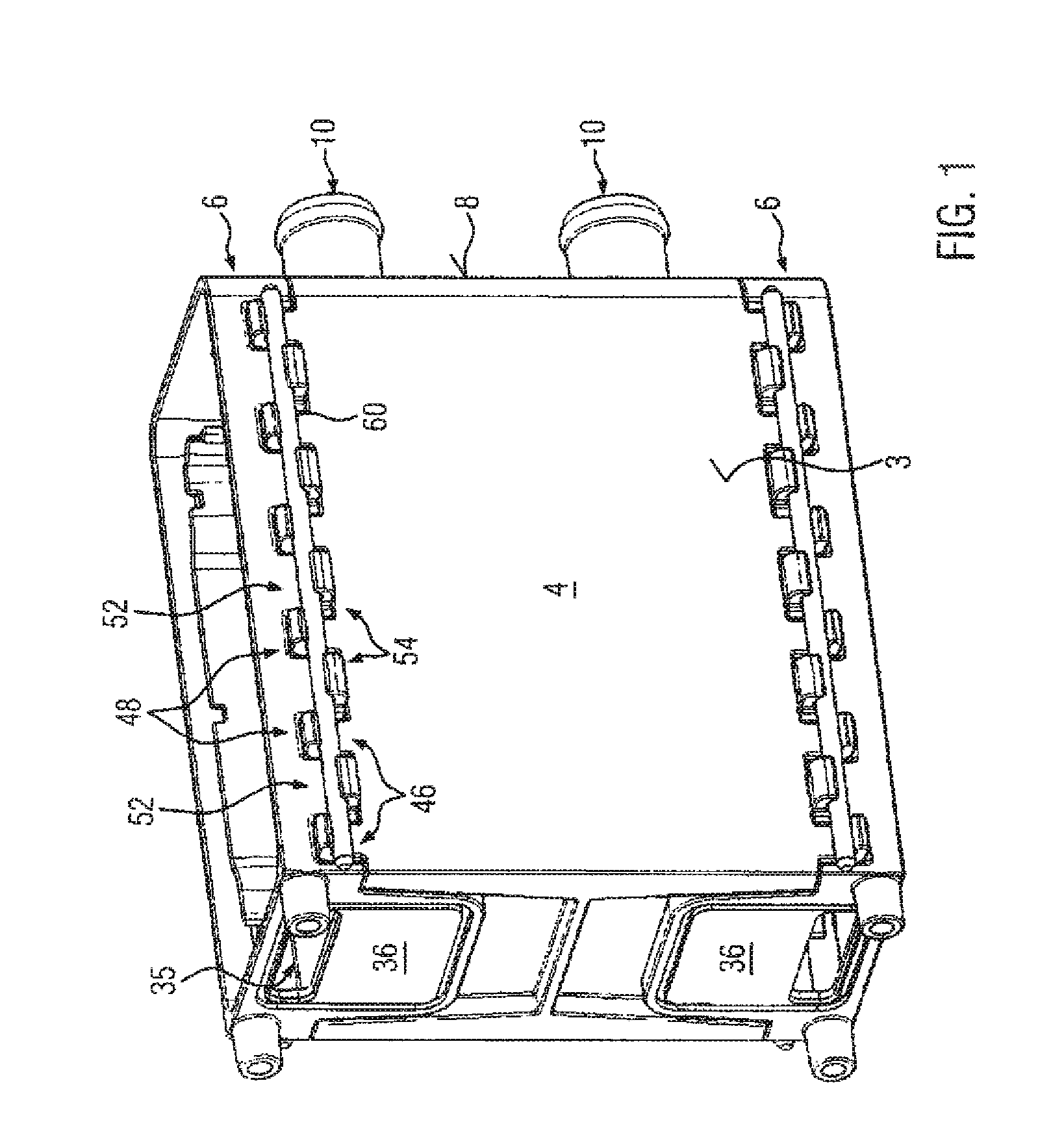
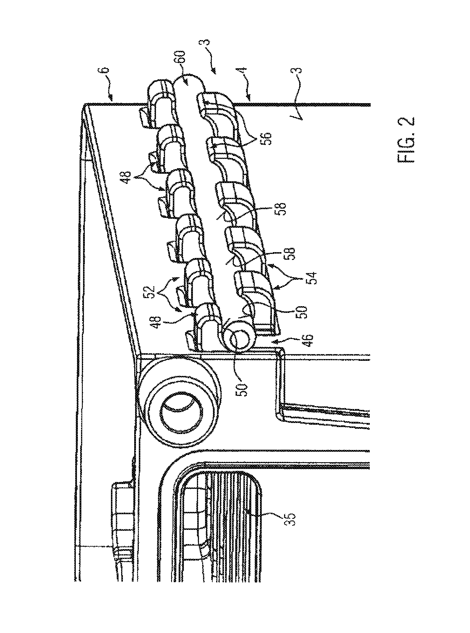
[0051]FIG. 1 shows a perspective view of a sealed housing 2 including a plane, straight outer wall 3 and configured here as three-part housing comprising a housing lower part 4 and two opposed housing covers 6. The housing covers 6 are configured identically and produced as aluminum pressure die castings. The housing lower part 4 is an injection molded plastic component provided with two parallel connection pieces 10 projecting from the first end face 8 thereof. As can especially be seen from FIGS. 3 and 4, the housing lower part 4 is formed integrally with these connection pieces 10 and is also formed integrally with a central partition 12 separating two circulation chambers 14a, 14b, which communicate with one another via a flow passage 16 formed in the partition thus allowing a flow from one connection piece 10 through the associated circulation chamber 14a, through the flow passage 16 and the other circulation chamber 14b, said flow being conducted out of the housing 2 through t...


PUM

PropertyMeasurementUnit
Forceaaaaaaaaaa
Electrical conductoraaaaaaaaaa

Abstract

A sealed housing of an electric heating device to be installed in a motor vehicle includes a housing lower part and a housing cover abutting on the housing lower part via an intermediate sealing element. An elongate positive locking element, which interconnects the housing lower part and the housing cover in a form fit manner, is provided between opposed contact surfaces of the housing lower part and a housing cover. The positive locking element abuts on the contact surfaces under a pretensioning force caused by compression of the sealing element. A method of producing a sealed housing also is disclosed via which the contact surfaces move into contact with the elongate positive locking element under a pretensioning force of the sealing element.

Description

BACKGROUND OF THE INVENTION[0001]1. Field of the Invention[0002]The present invention relates to a sealed housing of a device to be installed in a motor vehicle as well as to a method of producing the same.[0003]2. Description of the Related Art[0004]Sealed housings in motor vehicles may accommodate e.g. control devices which should be hermetically sealed in the housing in a dustproof manner. These devices are especially electronic control devices, which may be sensitive to contamination and environmental influences as well as humid air. A sealed housing according to the present invention may, however, also be a housing in which a medium is conducted and / or accommodated.[0005]Such a sealed housing is known e.g. from DE 196 42 442 A1. This publication discloses a sealed housing of an electric heating device comprising a housing lower part and a housing cover, which abuts on the housing lower part via an intermediate sealing element.[0006]EP 2 440 004 A1, which is owned by the present...

Claims


Application Information

Patent Timeline
IPC IPC(8): H05K5/06
CPCH05K5/069F24H3/0464F24H9/02F24H9/14Y10T29/49826
Inventor BOHLENDER, FRANZNIEDERER, MICHAEL
Owner WACKER NEUSON SE
Why Eureka
Try Eureka