Hydrodynamic clutch device

Active Publication Date: 2008-10-02
ZF FRIEDRICHSHAFEN AG
View PDF12 Cites 17 Cited by
  • Summary
  • Abstract
  • Description
  • Claims
  • Application Information

AI Technical Summary

Benefits of technology

[0011]When an axial contact element is assigned to the drive-side housing wall, especially to the axial recess in that wall, it is ensured—insofar as this axial contact element has a sufficient degree of hardness that no wear will occur on the axial contact surface of the drive-side housing wall, and that therefore the flow guide element will not be subjected to any undesirable play in the axial direction. It is especially preferable for the axial contact element to be made of spring steel. A solution of this type is especially favorable in cases where the flow guide element is also made of metal. The flow guide element is preferably made of a relatively hard metal such as a sintered material, and, since a sintering process can be used, the element can be produced easily. The carrier hub, which is held a certain axial distance away from the drive-side housing wall and from its axial contact surface by the flow guide element, can also be made of a s

Problems solved by technology

The disadvantage of the known hydrodynamic clutch device is the considerable expense which is associated with the housing hub mounted on the drive-side housing wall, because this housing hub not only must be dimensioned in the axial direction in such a way that it positions the hub, which holds the turbine wheel and/or a component of the torsional vibration damper axially with respe

Method used


Image

  • Hydrodynamic clutch device
  • Hydrodynamic clutch device
  • Hydrodynamic clutch device

Examples


Example

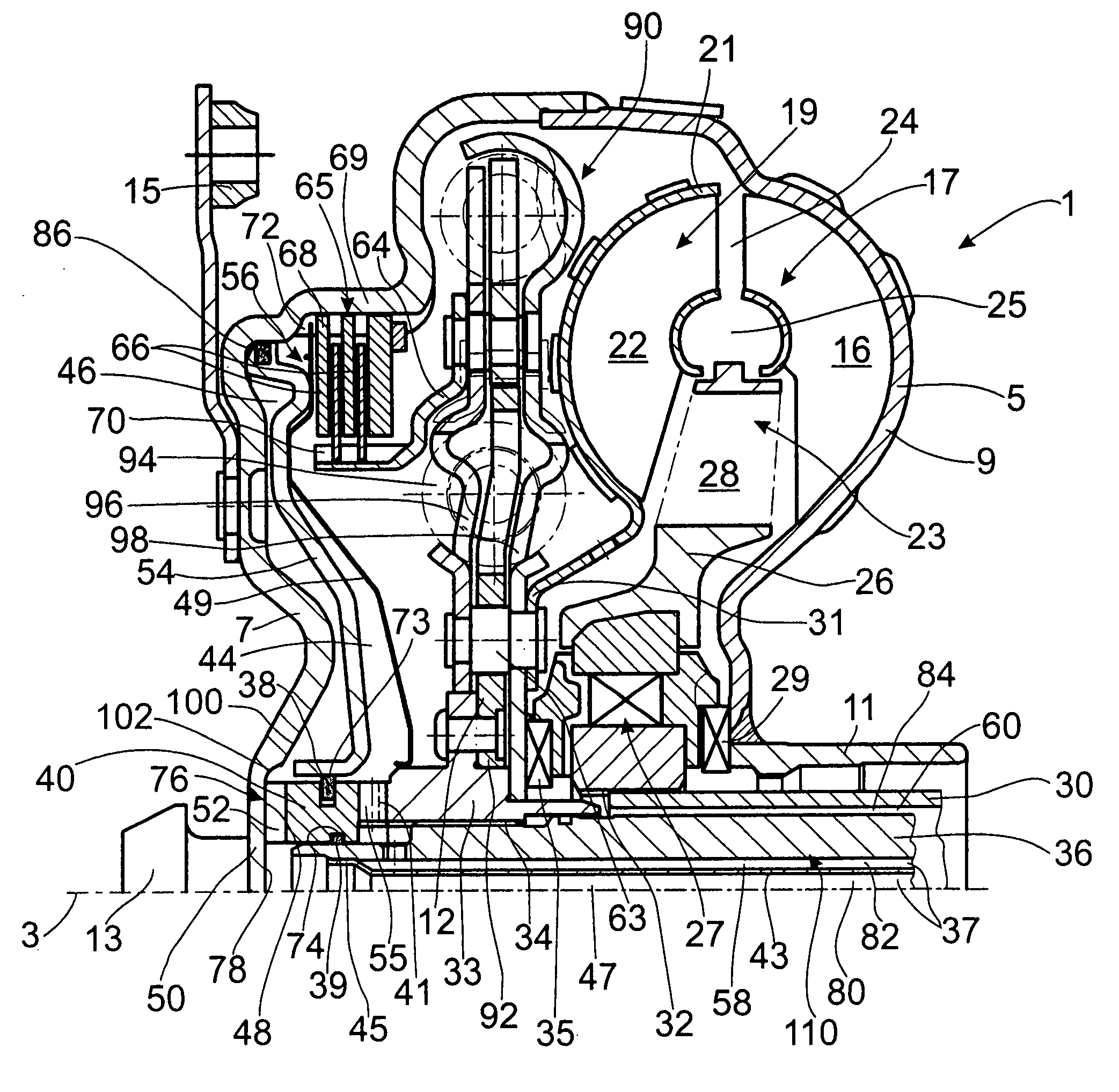
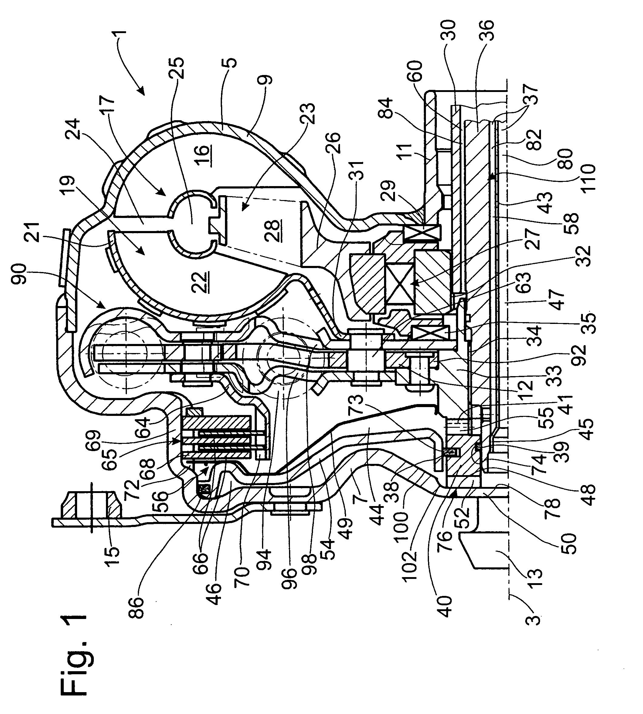
[0027]FIG. 1 shows a hydrodynamic clutch device 1, designed as a hydrodynamic torque converter. The hydrodynamic clutch device 1 has a clutch housing 5, which is able to rotate around an axis of rotation 3. On the side facing a drive (not shown), such as the crankshaft of an internal combustion engine, the clutch housing 5 has a drive-side housing wall 7, which is permanently connected to a pump wheel shell 9. This merges in the radially inner area with a pump wheel hub 11.

[0028]To return to the drive-side housing wall 7: On the side facing the drive (not shown), this wall has a bearing journal 13, which, in a manner which is already known and therefore not illustrated in detail, is supported on an element of the drive, such as the crankshaft, for the drive-side mounting of the clutch housing 5. In addition, the drive-side housing wall 7 has fastening mounts 15, which serve in the conventional manner to allow the clutch housing 5 to be fastened to the drive, preferably by way of a f...


PUM


Abstract

A hydrodynamic clutch includes a hydrodynamic circuit formed by at least a pump wheel and a turbine wheel in a clutch housing with a drive-side housing wall extending to the axis of rotation, and a bridging clutch with a piston capable of shifting axially relative to the drive-side housing wall. The turbine wheel is connected to a hub, which is connected for rotation in common to a takeoff, and is axially supported between the hydrodynamic circuit and a flow guide element, which is supported between the hub and the drive-side housing wall, and has first and second flow passages which are axially offset from each other. The flow guide element has a drive-side end with an axial bearing area which can be moved into axial contact with an axial bearing, which is either an axial contact surface on the drive-side housing wall or is assigned to the drive-side housing wall.

Description

BACKGROUND OF THE INVENTION[0001]1. Field of the Invention[0002]The invention pertains to a hydrodynamic clutch device of the type including a clutch housing which is rotatable about an axis of rotation and has a drive-side housing wall, a hydrodynamic circuit including a pump wheel and a turbine wheel in the clutch housing, and a bridging clutch having a piston capable of shifting axially relative to the drive-side housing wall, the piston separating a pressure space adjacent to the drive-side housing wall from a supply space.[0003]2. Description of the Related Art[0004]A hydrodynamic clutch device designed as a hydrodynamic torque converter is known from U.S. Pat. No. 5,964,320. A pump wheel cooperates with a turbine wheel and a stator to form a hydrodynamic circuit in a clutch housing; this circuit cooperates with a bridging clutch. The bridging clutch has a piston, which can be connected to a drive-side housing wall of the clutch housing and shifted in the axial direction. This ...

Claims


Application Information

Patent Timeline
IPC IPC(8): F16H45/02
CPCF16H45/02F16H2045/021F16H2045/0215F16H2045/0226F16H2045/0231F16H2045/0247F16H2045/0284
Inventor FREY, PETERBAUMANN, ROLANDGREULICH, MICHAELMENCHER, GEORGREINHARDT, BERNDHAMMER, PETERREDIGER, PATRICK
Owner ZF FRIEDRICHSHAFEN AG
Why Eureka
Try Eureka