Cast-in-situ concrete filling component

A technology of filling components and cast-in-place concrete, which is applied to building components, building structures, floor slabs, etc., can solve the problems of surface damage of solid lightweight material components, affecting the construction quality of the floor, and easy damage to the outer surface, reducing the The effect of production time, convenient construction and simple installation

Inactive Publication Date: 2014-10-08
陈风平
View PDF5 Cites 4 Cited by
  • Summary
  • Abstract
  • Description
  • Claims
  • Application Information

AI Technical Summary

Problems solved by technology

However, when this kind of membrane shell component is applied to the floor, the membrane shell cannot be accurately arranged in the middle layer of the floor, which affects the construction quality of the floor
However, the strength of the outer surface of this type of membrane shell member is not enough. Even if cement or cement mortar or cement fiber or cementitious material reinforcement or net is used, the outer surface will still be damaged during actual handling, stacking, transportation, installation and construction. It is easy to be damaged, and in severe cases, the appearance of the internal solid lightweight material components will be damaged, and the impact resistance is not ideal

Method used


Image

  • Cast-in-situ concrete filling component
  • Cast-in-situ concrete filling component
  • Cast-in-situ concrete filling component

Examples


Embodiment Construction

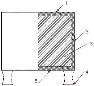
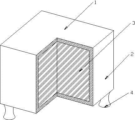
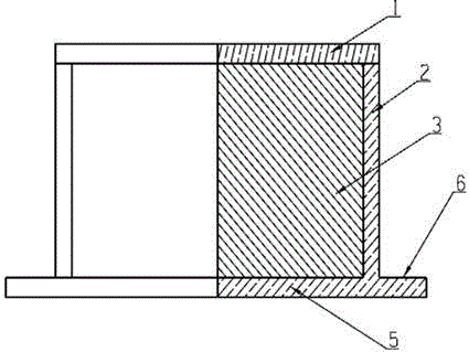
[0019] The present invention comprises a cover plate 1, surrounding sides 2, lower bottom plate 5, filling material 3, such as figure 1 , figure 2 As shown, it is a cavity with an opening formed by the lower bottom plate 5 and the surrounding sides 2, and the filling material 3 is inserted into the cavity, and then the lower bottom plate 5 and the surrounding sides 2 are surrounded by the opening end of the hollow shell and the cover plate 1 connection, so that the cover plate, the surrounding side 2, the lower bottom plate 5, and the filler are sealed and stacked into a solid whole. The shell formed by the cover plate 1, the surrounding sides 2, and the lower bottom plate 5 contains cement concrete, early Strong agent, quick-setting agent, bubble seal, cellulose ether, polycarboxylate high-performance water reducer, polymer anti-cracking mortar, at least one or more or all of them; the filling material 3 is formed by AB foam Hard resin, polystyrene sheet mixed extrusion. ...


PUM


Abstract

A cast-in-situ concrete filling component comprises a sealing cover plate, a peripheral side face, a lower bottom plate and filling materials, and is characterized in that the filling materials are arranged in a cavity with an opening, the cavity is defined by the lower bottom plate and the peripheral side face, the opening of the cavity defined by the lower bottom plate and the peripheral side face is connected with the sealing cover plate, and the sealing cover plate, the peripheral side face, the lower bottom plate and the filling materials are sealed and overlapped to form a whole solid; a shell defined by the sealing cover plate, the peripheral side face and the lower bottom plate contains at least one of or more than one of or all of cement concrete, early strength agents, accelerating agents, sodium silicate, cellulose ether, polycarboxylate-type high-performance water reducing agents and polymer anti-crack mortar; the filling materials are formed by AB foam forming stearin and polyphenyl boards in a coextrusion mode. In addition, a protruding fixed component can be arranged on the face of the lower bottom plate according to the technological base or a formwork stretching outwards is arranged on the side face of the periphery of the lower bottom plate or chamfers are arranged along the periphery of the lower bottom plate and the periphery of the sealing cover plate. The cast-in-situ concrete filling component has the advantages of being easy and convenient to install, high in production efficiency, low in construction cost, high in seismic crack resistance and crush resistance, high in surface hardness and the like.

Description

technical field [0001] The invention relates to a pre-installed filling component used in cast-in-place floor coverings, and a cast-in-place concrete filling piece. Background technique [0002] At present, the application of cast-in-place concrete floor is more extensive, and the application number is 200610008747.7, and the title is "a kind of membrane shell component" disclosed invention technology, and it is to comprise upper board, surrounding side wall, lower bottom board, upper board, surrounding side wall The lower bottom plate encloses a hollow body, which is characterized in that there is a light material block in the cavity surrounded by the upper plate, surrounding side walls and lower bottom plate to form a solid whole with the upper plate, surrounding side walls and lower bottom plate. However, when this type of membrane shell component is applied to the floor, the membrane shell cannot be accurately arranged at the middle layer of the floor, which affects the ...

Claims


Application Information

Patent Timeline
Patent Type & Authority Applications(China)
IPC IPC(8): E04B5/17E04B5/38
Inventor 陈风平
Owner 陈风平
Why Eureka
Try Eureka