Heat exchanger

A technology of heat exchangers and grooves, which is applied to heat exchange equipment, heat exchanger shells, indirect heat exchangers, etc., and can solve problems such as leakage and openings

Inactive Publication Date: 2013-09-11
DANFOSS AS
View PDF8 Cites 4 Cited by
  • Summary
  • Abstract
  • Description
  • Claims
  • Application Information

AI Technical Summary

Problems solved by technology

However, there is still a risk of leakage when the heat exchanger plate is deformed under pressure in one of the flow paths, when t

Method used


Image

  • Heat exchanger
  • Heat exchanger
  • Heat exchanger

Examples


Embodiment Construction

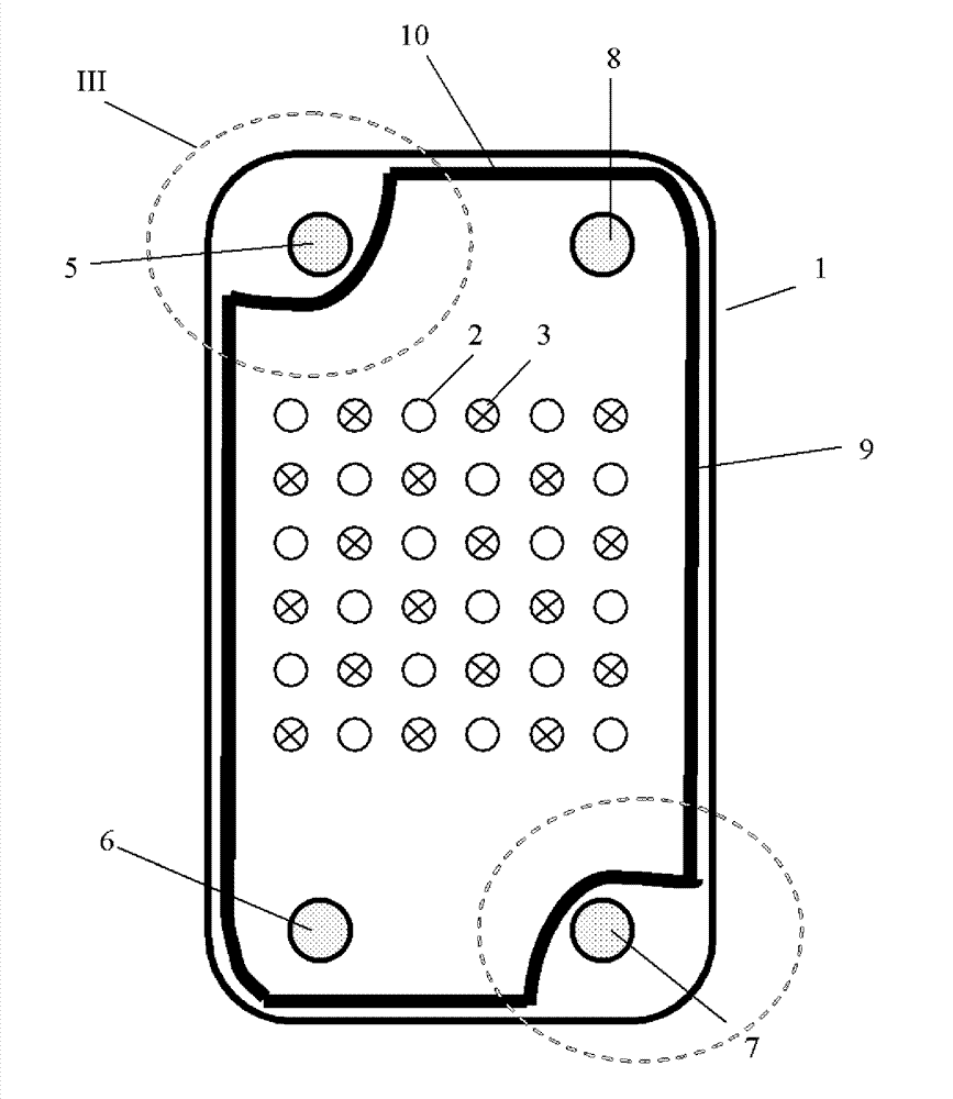
[0027] figure 1 A heat exchanger plate 1 is shown. The heat exchanger plate 1 comprises a raised portion 2 which rises a given height above the plane of the heat exchanger plate 1 . Furthermore, the heat exchanger plate 1 includes a hollow portion 3 sunk to a given depth in this heat exchanger plate 1 . Protrusions 2 are marked with open circles, while hollows 3 are marked with crossed circles.

[0028] As is known in the art, two such heat exchanger plates 1 when stacked on top of each other form a pair of plates. Two such adjacent plates will usually be shaped slightly differently so that when they are stacked, the raised portion 2 of one plate fits into the hollow portion 3 of the adjacent plate, and so on.

[0029] Flow paths are formed in these pairs in this way. Usually the flow paths formed on one side of the heat exchanger plate 1 will belong to the first flow path and the flow paths formed on the opposite side will belong to the second flow path which is sealed fr...


PUM


Abstract

A heat exchanger is provided comprising a stack of heat exchanger plates (1, 1a, 1b, 1 c) formed of sheet metal having a three-dimensional structured pattern (2, 3), each heat exchanger plate (1,1 a, 1b, 1 c) having a groove (10), a gasket (9) being arranged in said groove (10) and resting against an adjacent heat exchanger plate (1 a), said groove (10) having a bottom inner surface (11), said inner surface bottom (11) having at least a protrusion (14, 15) directed to said adjacent heat exchanger plate (1a). It is intended to minimize the risk of a leakage. To this end in the region of said protrusion (14, 15) said gasket (9) is compressed more than in a region out of said protrusion (14, 15).

Description

technical field [0001] The invention relates to a heat exchanger comprising: a stack of heat exchanger plates formed from metal sheets having a three-dimensional structural pattern, each heat exchanger plate having a groove arranged in said groove and abutting against an adjacent heat exchanger plate. A gasket for an exchanger plate, said groove having a bottom with at least a protrusion directed towards said adjacent heat exchanger plate. Background technique [0002] Such a heat exchanger is known from US7490660B2. The gasket has grooves that fit the protrusions. On the side facing the adjacent heat exchanger plate, the gasket has a protrusion that fits into a groove formed on the underside of the adjacent heat exchanger plate. The groove is the negative form of the protrusion on the upper side of the adjacent heat exchanger plate. [0003] The space between a heat exchanger plate and an adjacent heat exchanger plate forms part of a primary flow path or part of a second...

Claims


Application Information

Patent Timeline
IPC IPC(8): F28D9/00F28F9/00
CPCF28F3/10F16J15/10F16J15/062F16J15/104F28F3/08
Inventor L.珀森
Owner DANFOSS AS
Why Eureka
Try Eureka