Vehicle interior accessory retainer

a technology for accessories and retainers, which is applied in the direction of machine supports, transportation and packaging, and other domestic objects, can solve the problems of decreasing the retaining load of linear springs, and achieve the effect of preventing the reduction of the retaining load and resisting deterioration with ag

Inactive Publication Date: 2010-05-18
MURAKAMI CORP
View PDF12 Cites 17 Cited by
  • Summary
  • Abstract
  • Description
  • Claims
  • Application Information

AI Technical Summary

Benefits of technology

[0010]An object of the present invention is therefore to provide a vehicle interior accessory retainer capable of securely retaining an accessory, resistant to deterioration with age and by heat, and capable of preventing reduction in the retaining load.
[0012]In the vehicle interior accessory retainer according to the present invention, the upper opening and the front opening are formed in the base inner. The provision of this upper opening permits the base inner to be mounted on the base, and the provision of the front opening permits the base inner to be mounted as slid onto the base; therefore, they facilitate an assembling work.
[0013]The plate spring is used for the base inner to retain the base. This plate spring has the planar portion arranged along the upper surface of the lower part in the base inner, and the upright portions formed as standing upright from the both sides of the planar portion and arranged along the side walls in the base inner. For this reason, it can be securely mounted along the side walls and the lower part in the base inner. In addition, the base-retaining pieces are formed as directed inward from the upright portions and the base-retaining pieces retain the base in the base inner. Since the base is retained by the plate spring in this manner, the base inner becomes unlikely to deteriorate with age and by heat, and thus the retaining force can be maintained. Therefore, it is feasible to prevent reduction in the retaining load.
[0015]When the stay mount part has the projection projecting from the lower part toward the upper part of the base inner as described above, it is feasible to prevent an increase in the size of the base inner itself even if the stay mount part becomes large. In this form, there is a concern about interference between the plate spring and the stay mount part, but the interference between the plate spring and the stay mount part can be prevented because the through hole for letting the projection in the stay mount part pass is formed in the plate spring. In addition, the planar portion in the plate spring is provided with the tension applying part for applying the tension between the upper surface of the lower part in the base inner and the projection in the stay mount part. For this reason, the plate spring can be mounted more securely on the base inner. In addition, since the nip part for nipping the planar portion in the plate spring is formed between the projection and the lower part of the base inner, the plate spring can be mounted still more securely on the base inner.
[0017]Furthermore, the vehicle interior accessory retainer can be constructed in a form wherein a load adjusting structure is formed in the upright portions in the plate spring. When this load adjusting structure is formed, it becomes easy to perform load design according to materials of the base inner, the plate spring, and so on.
[0020]The vehicle interior accessory retainer according to the present invention is able to securely retain the accessory, resistant to deterioration with age and by heat, and able to prevent reduction in the retaining load.

Problems solved by technology

For this reason, it had the problem that if the base inner deteriorated with age or by heat, the retaining load by the linear spring decreased, so as to degrade vibration resistance.

Method used


Image

  • Vehicle interior accessory retainer
  • Vehicle interior accessory retainer
  • Vehicle interior accessory retainer

Examples


Embodiment Construction

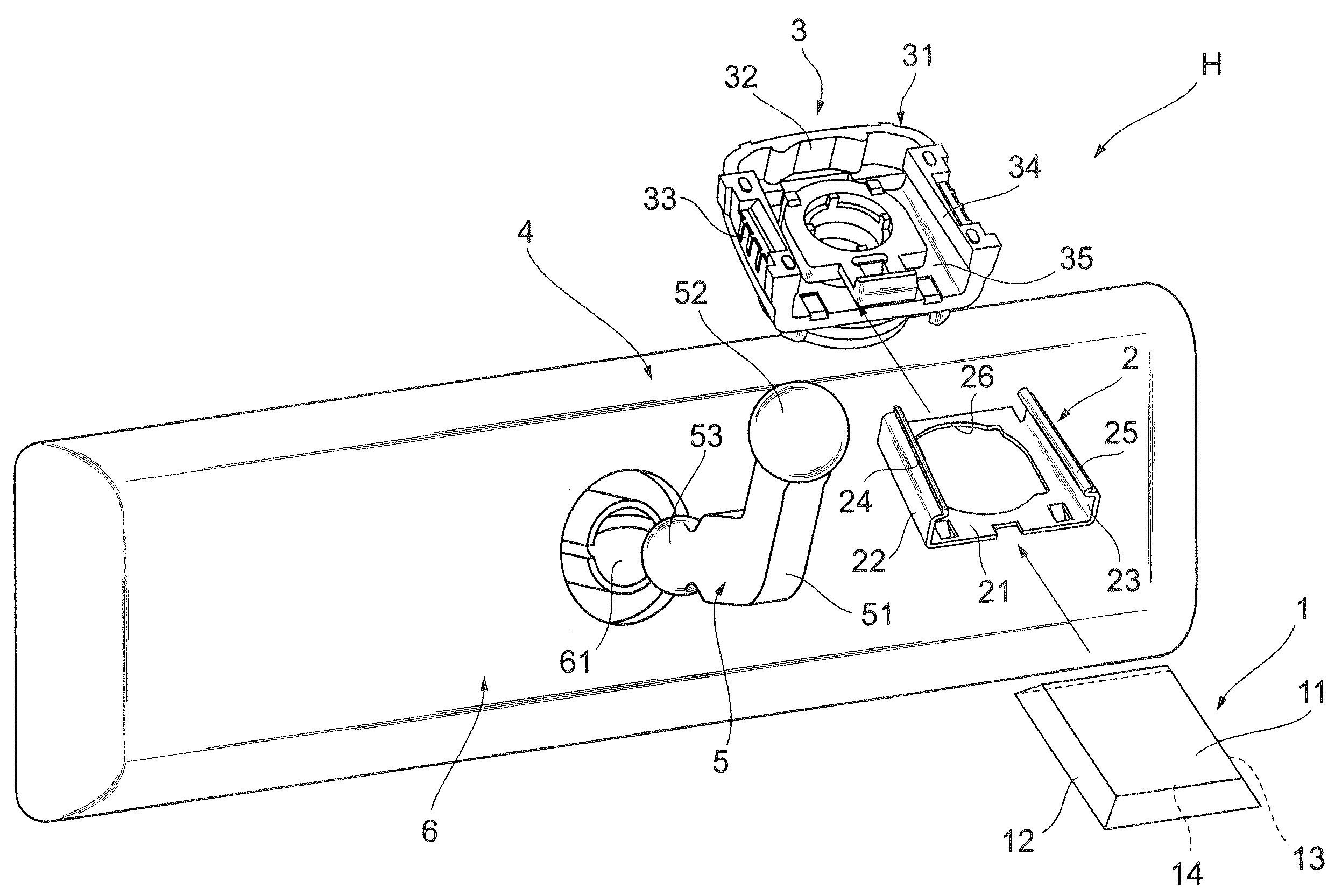
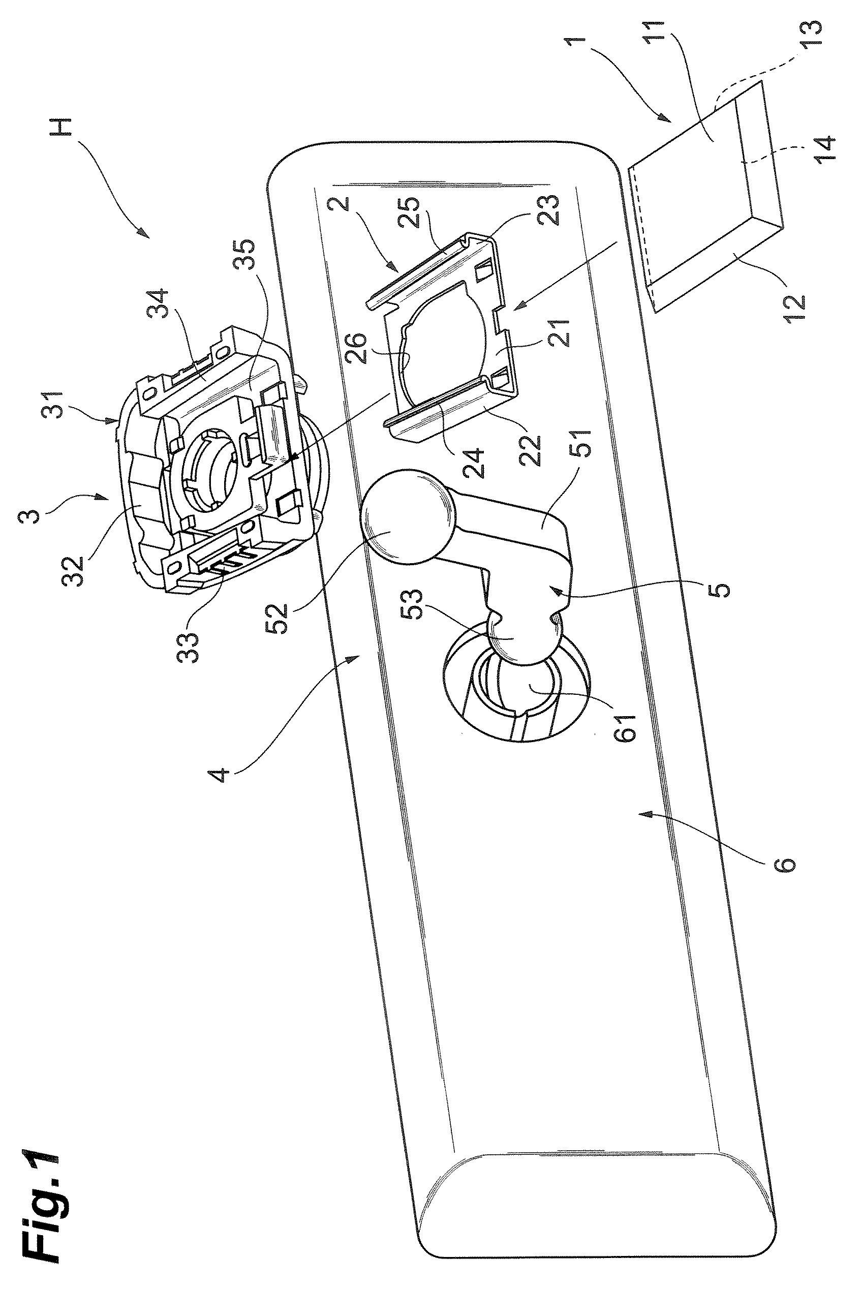
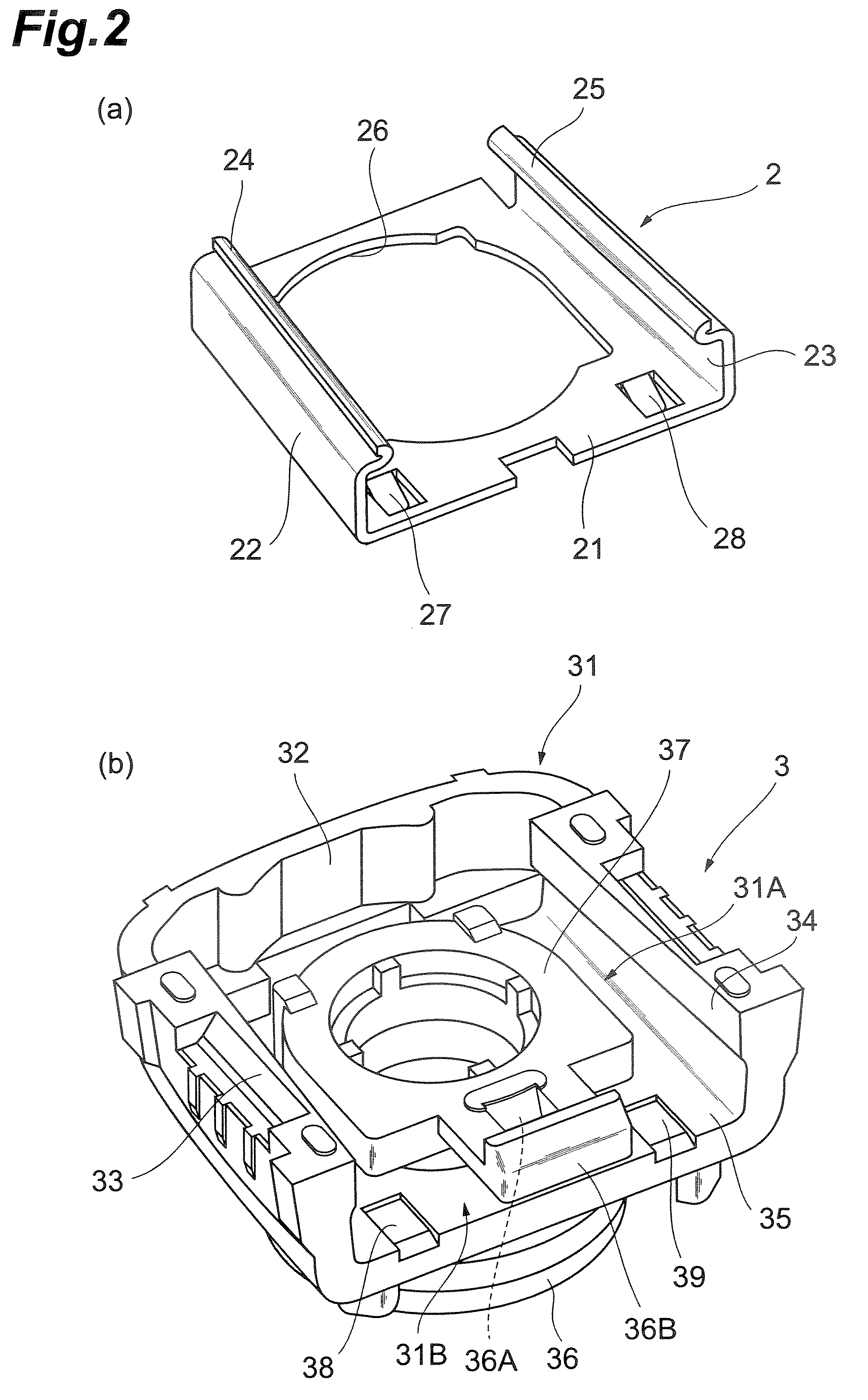
[0030]An embodiment of the present invention will be described below with reference to the drawings. FIG. 1 is an exploded perspective view of a vehicle interior accessory retainer according to the present invention, FIG. 2(a) a perspective view of a plate spring, FIG. 2(b) a perspective view of a base inner, FIG. 3 a plan view of the base inner, FIG. 4 a sectional view corresponding to a cross section along line IV-IV in FIG. 3 in a state in which the plate spring is incorporated in the base inner and in which the base inner is mounted on the base, and FIG. 5 a sectional view corresponding to a cross section along line V-V in FIG. 3 in a state in which the plate spring is incorporated in the base inner and in which the base inner is mounted on the base.

[0031]As shown in FIG. 1, the vehicle interior accessory retainer H according to the present embodiment is composed of a base 1, a plate spring 2, a base inner 3, and a mirror assembly 4.

[0032]The base 1 is, for example, a metal memb...


PUM


Abstract

A vehicle interior accessory retainer includes a base, a base inner and a plate spring. In the base inner, upper and front openings are formed in upper and front parts, respectively, side walls are formed in side parts in the upper opening, a lower part is formed at a position opposite to the upper opening with the side walls in between, and a stay mount part is provided in the lower part. The plate spring has a planar portion, upright portions, and base-retaining pieces. The stay mount part has a projection. A nip part is formed between the projection and the lower part of the base inner. A through hole is formed in the planar portion in the plate spring. A tension applying part is formed between the upper surface of the lower part in the base inner and the projection in the stay mount part.

Description

BACKGROUND OF THE INVENTION[0001]1. Field of the Invention[0002]The present invention relates to a vehicle interior accessory retainer for retaining an accessory in a vehicle interior, e.g., a vehicle interior mirror or a television camera.[0003]2. Related Background Art[0004]A vehicle interior mirror for rearview is provided in a vehicle interior. Recently, there are cases where the vehicle interior mirror, a television camera, etc. are provided in the vehicle interior, in order to improve the functionality of vehicle. Such an accessory is attached to a part of the vehicle interior, e.g., a ceiling or an instrument panel. These accessories are structured so as to be detached from the mount part in the vehicle interior, in order to prevent breakage thereof upon exertion of large impact, e.g., collision with an occupant's head in the event of vehicle collision or the like.[0005]However, if during normal times the accessory is easily detached from the mount part in the vehicle interio...

Claims


Application Information

Patent Timeline
Patent Type & Authority Patents(United States)
IPC IPC(8): F16M13/00
CPCB60R1/04
Inventor TANAKA, YOSHITOITO, MASAHIKONAKAZAWA, YOSHITAKEFUKAI, AKIRA
Owner MURAKAMI CORP
Why Eureka
Try Eureka