
Medical Catheter Tubes and Process for Production Thereof

Inactive Publication Date: 2009-09-17
KANEKA CORP
View PDF7 Cites 7 Cited by
  • Summary
  • Abstract
  • Description
  • Claims
  • Application Information

AI Technical Summary

Benefits of technology

[0036]The aspects above, the other aspects and the advantageous effects of the invention will be described below more specifically in the following embodiments.
[0037]The present invention provides a thin medical catheter tube superior in stretch resistance, kink resistance, and lumen lubricity. In particular, the present invention provides a catheter tube resistant to deterioration in operational convenience, i.e., resistant to elongation by usage or operation during surgery and also to deterioration in lumen lubricity during device insertion, and a production method of the catheter tube.

Problems solved by technology

However, the methods disclosed in the Patent Documents 1 to 3 gave catheters unsatisfactory in tensile strength because of absence of orientation and also in lumen lubricity during insertion or withdrawal of the guide wire because of separation of the PTFE particles.
In addition, the catheters obtained by the method disclosed in the Patent Documents 1 to 3, which are not oriented, were unsatisfactory in kink resistance and positional adjustment efficiency (including stretch resistance and torque-transmitting efficiency).
Further, it was necessary to repeat coating and sintering of a dispersion several times before obtaining a PTFE tube having a desired wall thickness, which caused problems of low productivity and local fluctuation in thickness by uneven coating.

Method used

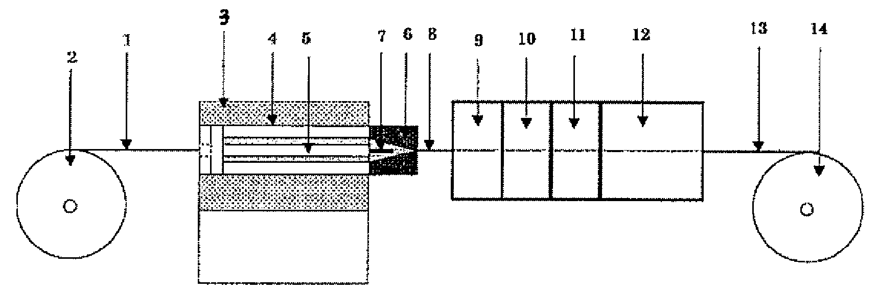
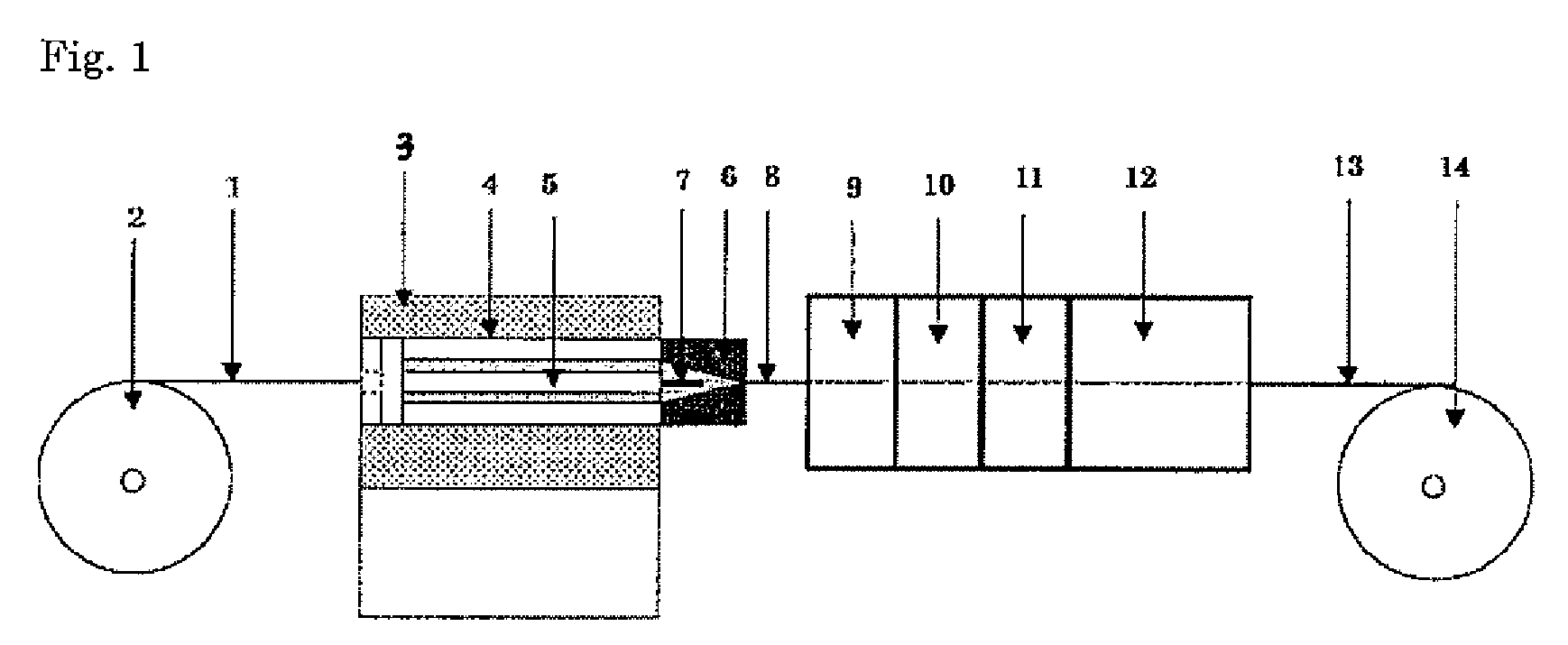

Image

  • Medical Catheter Tubes and Process for Production Thereof
  • Medical Catheter Tubes and Process for Production Thereof

Examples


example 1

[0095]100 wt parts of a PTFE fine powder A (product name: Polyflon PTFE F-207, produced by Daikin Industries, Ltd) and 56 wt parts of a lubricant A (product name: Kosei Sol FC-1, available from Kosei Trading Co. Ltd., boiling point: 120° C., interfacial tension: 15.5 dyne / cm) were placed in a glass bottle; the mixture was left still in a constant temperature oven at 50° C. for 24 hours for aging, and then, cooled to room temperature and mixed by shaking. After mixing, the mixture was compressed at a pressure of 1.0 MPa for 5 minutes in a performing cylinder of 18 mmφ in width for preparation of a preform. The primary preform obtained was placed in the cylinder of an extrusion molding machine and preformed additionally at a pressure of 28 MPa for 30 seconds with the head closed, for removal of air bubbles in the preform. The internal diameter of the extruder cylinder 4 in the paste extruder 3 was 18 mm; the external diameter of the extruder mandrel 5 was 12 mm; a die 6 having an inte...

example 2

[0098]A PTFE thin-film tube was prepared in a similar manner to Example 1, except that

[0099]56 wt parts of a lubricant B (product name: Fluorinert FC-40, available from Sumitomo 3 M Ltd., boiling point: 155° C., surface tension: 16.0 dyne / cm) was added. The moldability during paste extrusion was rated ◯. The tensile strength of the PTFE thin-film tube obtained, as determined at a displacement of 1.0 mm, was 7.6 N / mm2. The kink length determined was 42 mm. The stress after one reciprocation in the lumen lubricity test was 0.45N, while that after 50 reciprocations was 0.47N.

example 3

[0100]A PTFE thin-film tube was prepared in a similar manner to Example 1, except that

[0101]56 wt parts of a lubricant C (product name: Fluorinert FC-43, manufactured by Sumitomo 3 M Ltd., boiling point: 174° C., surface tension: 16.0 dyne / cm) was added. The moldability during paste extrusion was rated ◯. The tensile strength of the PTFE thin-film tube obtained, as determined at a displacement of 1.0 mm, was 6.4 N / mm2. The kink length determined was 45 mm. The stress after one reciprocation in the lumen lubricity test was 0.43N, while that after 50 reciprocations was 0.45N.


PUM

PropertyMeasurementUnit
Lengthaaaaaaaaaa
Thicknessaaaaaaaaaa
Pressureaaaaaaaaaa

Abstract

A medical catheter tube containing a tetrafluoroethylene polymer, which has a wall thickness of 0.1 mm or below and exhibits a tensile strength (S1) at 1.0 mm displacement of 5.0 N / mm or above; and a process for the production of medical catheter tubes, characterized by molding a composition both a tetrafluoroethylene polymer and a lubricant having high affinity for the polymer by paste extrusion. The invention provides thin-wall medical catheter tubes excellent in elongation resistance, kink resistance and internal cavity lubricity.

Description

TECHNICAL FIELD[0001]The present invention relates to a catheter tube containing a tetrafluoroethylene polymer (hereinafter, referred to as “PTFE”) favorably used in medical organizations such as hospitals and a production method of the catheter tube.CROSS REFERENCE TO RELATED APPLICATIONS[0002]All disclosures including description, claims, drawings, and abstract in Japanese Patent Application 2005-302099 (filed on Oct. 17, 2005) and Japanese Patent Application 2006-010472 (filed on Jan. 18, 2006) are hereby incorporated by reference.BACKGROUND ART[0003]Less-invasive intravascular operation of inserting a catheter percutaneously into the blood vessel for treatment of vascular lesion is mainly practiced recently for reduction of physical and temporal loads applied on patients. Examples of such operation include a percutaneous blood vessel-forming operation of enlarging the stricture site of blood vessel or removing thrombus from thrombus-clotted blood vessel by applying negative pres...

Claims


Application Information

Patent Timeline
IPC IPC(8): A61M25/00B29D23/00B29C48/09B29C48/32B29C48/475
CPCA61L29/041A61M25/0009B29C47/0004B29C47/0026B29C47/0057B29C47/02B29C47/20B29L2031/7542B29C47/54B29C67/04B29K2027/18B29L2023/005C08L27/18B29C48/15B29C48/022B29C48/10B29C48/0018B29C48/32B29C48/475B29C48/09A61L29/00A61M25/00
Inventor INAMOTO, SATOSHINAKAO, FUMIHIKOKOROGI, MITSUHARUMIHAYASHI, TSUYOSHI
Owner KANEKA CORP
Learn More