
Lead frame, resin package, semiconductor device and resin package manufacturing method

a manufacturing method and resin technology, applied in semiconductor devices, semiconductor/solid-state device details, electrical devices, etc., can solve problems such as affecting the quality of the manufactured resin package, and achieve the effects of high quality, high quality of the resin package, and resistance to deterioration of the semiconductor elemen

Active Publication Date: 2010-02-25
SUMITOMO CHEM CO LTD
View PDF15 Cites 7 Cited by
  • Summary
  • Abstract
  • Description
  • Claims
  • Application Information

AI Technical Summary

Benefits of technology

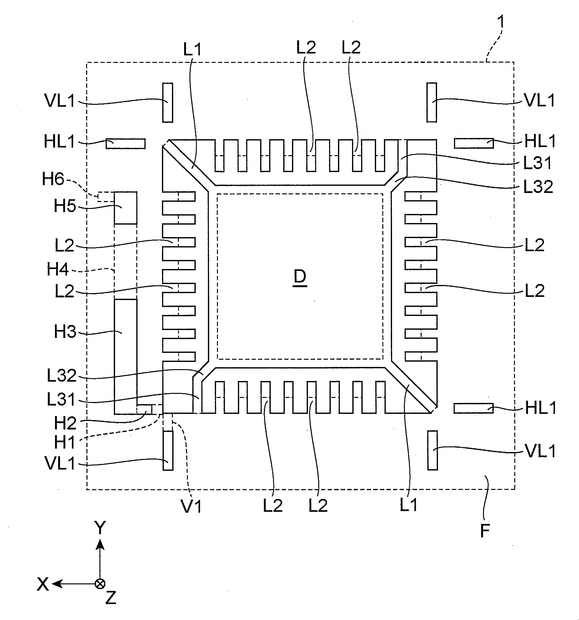
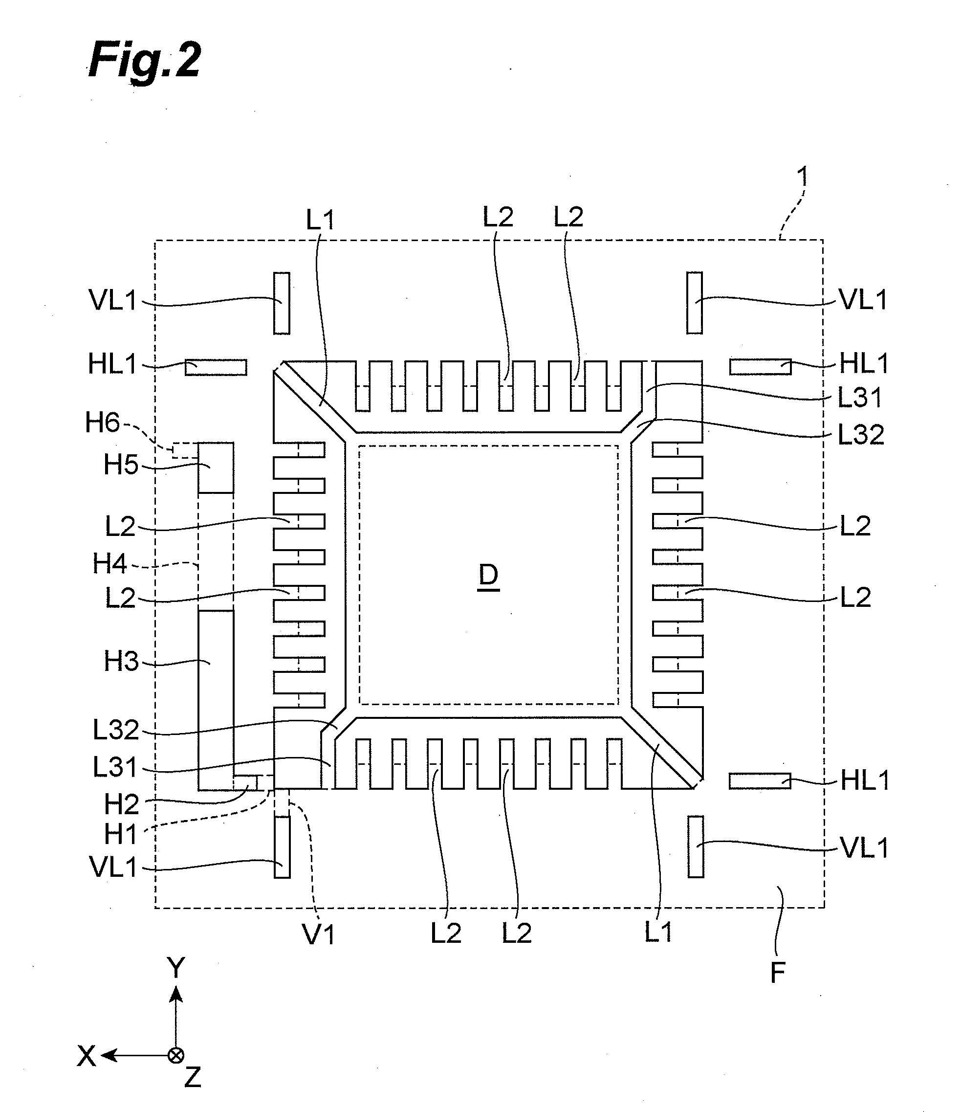
[0010]When the lead frame is sandwiched between molds during resin injection and a resin material is injected from one corner into the space between the molds, the resin converges at a corner located on a line extending diagonally from this corner, but the excess resin reservoir communicates with this corner via the pressure loss section. That is, because the resin material that tends to accumulate in the corner is transported to the excess resin reservoir by means of the pressure loss section, not only is weld formation suppressed at the corner, but since the minimum value S1 of the opening area of the pressure loss section perpendicular to the direction of flow of the resin is small, the pressure loss section is able to maintain the resin pressure at a suitable level in the corner so that the resin material fills every part of the mold in that area.
[0021]The lead frame of the present invention makes it possible to form a high-quality resin package, and a resin package manufactured using the lead frame of the present invention is of high quality.

Problems solved by technology

The inventors in this case investigated lead frames to resolve these problems, and discovered that with conventional lead frames, the injected resin material divides into a plurality of resin streams as it flows from the injection site, and that welds tend to occur at the confluences, detracting from the quality of the manufactured resin package.

Method used


Image

  • Lead frame, resin package, semiconductor device and resin package manufacturing method
  • Lead frame, resin package, semiconductor device and resin package manufacturing method
  • Lead frame, resin package, semiconductor device and resin package manufacturing method

Examples


example 1

[0083]The lead frame shown in FIGS. 2 and 3 was prepared, and this lead frame was black-oxide treated by being immersed in an aqueous solution containing sodium chlorite, trisodium phosphate and sodium hydroxide. Next, the black-oxide treated lead frame was arranged in the space between molds M1 and M2. The molds were heated, and the space between the molds was filled with liquid crystal polymer (Sumitomo Chemical E6008, flow initiation temperature T2=320° C.) when the temperatures (T1) of both molds M1 and M2 reached 300° C. The molds were then cooled, and once the mold temperatures reached 252° C. the molded resin package was removed from the molds.

example 2

[0084]A resin package was manufactured as in Example 1 except that a lead frame having a through hole substituted for groove H6 formed by half-etching was used as the lead frame shown in FIGS. 2 and 3.

example 3

[0085]A resin package was manufactured as in Example 1 except that a lead frame having a through holes substituted for excess resin reservoir H4 and groove H6 was used as the lead frame shown in FIGS. 2 and 3.


PUM


Abstract

A pressure loss section H1 (H2) extends from a position corresponding to a corner of a resin package, and S1 is the minimum value of the opening area of the pressure loss section H1 (H2) perpendicular to the direction of resin flow (X axis) in the pressure loss section H1 (H2) during resin molding, while S2 is the average value of the opening areas of excess resin reservoirs H3 to H5 perpendicular to the direction of resin flow (Y axis) within excess resin reservoir H3 to H5 during molding. In this lead frame, S1<S2 is satisfied.

Description

BACKGROUND OF THE INVENTION[0001]1. Field of the Invention[0002]The present invention relates to a lead frame, a resin package, a semiconductor device, and a resin package manufacturing method.[0003]2. Related Background Art[0004]Conventionally, a lead frame comprises a central die pad that is fixed to the main body of the lead frame by means of four suspended leads extending from the main body along the diagonal lines of the die pad. A plurality of die bonding leads are arranged around the die pad. The suspended leads may also be constructed so as to connect the die pad body to the outer frame.[0005]Such a lead frame is described for example in Japanese Patent Application Laid-open No. H5-315512. The lead frame described in Japanese Patent Application Laid-open No. H5-315512 is provided with an open region through which resin material can escape when resin material is injected into the mold during resin molding.[0006]However, resin packages manufactured using conventional lead fram...

Claims


Application Information

Patent Timeline
Patent Type & Authority Applications(United States)
IPC IPC(8): H01L23/495H01L21/56
CPCH01L21/565H01L23/3107H01L2924/01019H01L24/49H01L24/48H01L2924/01079H01L23/49541H01L23/49548H01L23/49565H01L2224/48091H01L2224/48247H01L2224/49175H01L2924/01012H01L2924/0102H01L2924/01078H01L2924/00014H01L2924/00H01L2924/181H01L2224/45099H01L2224/45015H01L2924/207
Inventor MATSUMI, YASUOMAEDA, MITSUO
Owner SUMITOMO CHEM CO LTD
Learn More