Image forming apparatus and method of performing density correction

a technology of density correction and image forming apparatus, which is applied in the direction of electrographic process apparatus, instruments, optics, etc., can solve the problem of image quality deterioration upon printing

Inactive Publication Date: 2011-01-04
OKI DATA CORP
View PDF3 Cites 2 Cited by
  • Summary
  • Abstract
  • Description
  • Claims
  • Application Information

AI Technical Summary

Benefits of technology

[0008]As described above, in the image forming apparatus of the present invention, when the developer density of the first pattern for detecting the developer density is greater than the threshold value, the second pattern for discarding developer is formed to discard the developer that is deteriorated. Afterward, the third pattern for the density correction is formed to perform the density correction. Accordingly, even when density abnormality occurs due to deterioration of developer, it is possible to properly perform the density correction. As a result, it is possible to reproduce a proper density, proper hue, and the like of an image.

Problems solved by technology

Accordingly, when the conventional image forming apparatus performs a printing operation, image quality tends to deteriorate upon printing.

Method used


Image

  • Image forming apparatus and method of performing density correction
  • Image forming apparatus and method of performing density correction
  • Image forming apparatus and method of performing density correction

Examples


first embodiment

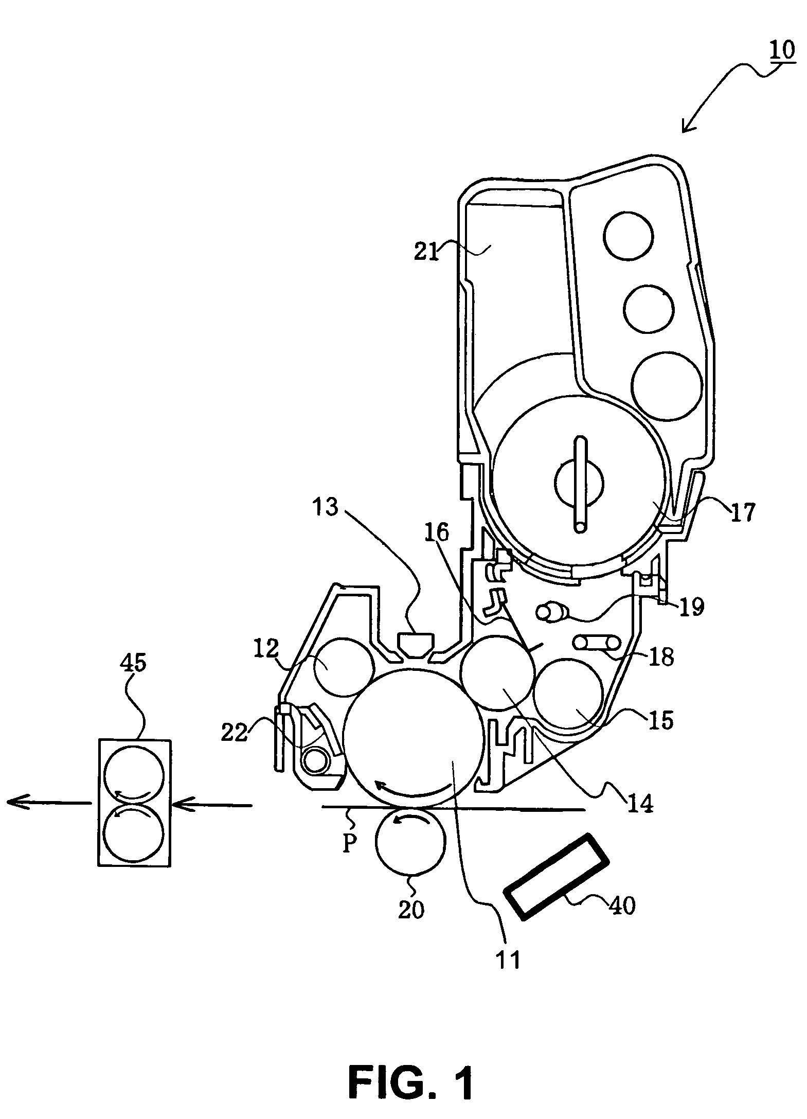
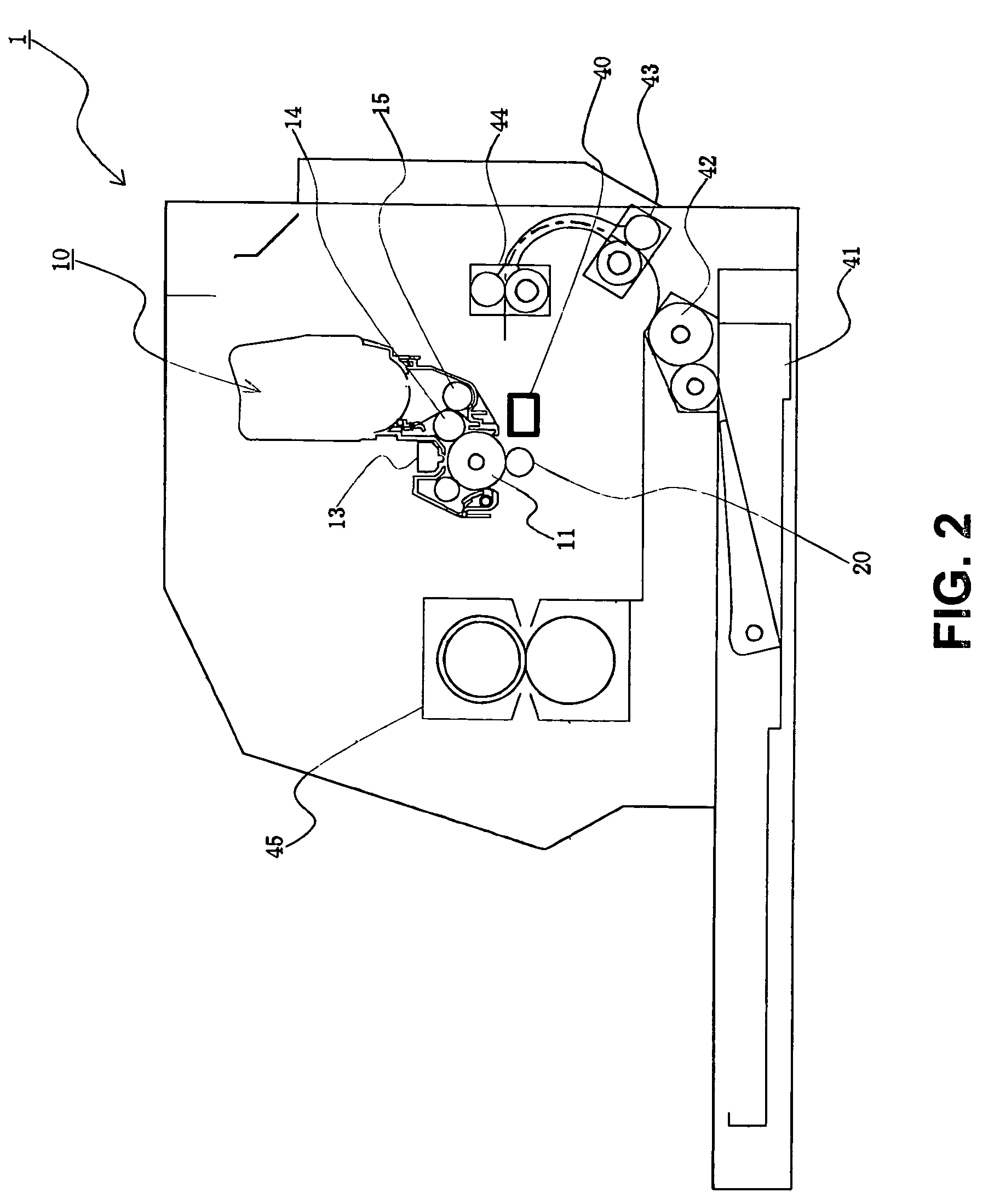
[0030]A first embodiment of the present invention will be explained. FIG. 1 is a schematic sectional view showing an image forming unit 10 according to the first embodiment of the present invention. FIG. 2 is a schematic sectional view showing an image forming apparatus 1 according to the first embodiment of the present invention.

[0031]In the embodiment, the image forming apparatus 1 may be a printer, a copier, a facsimile, a multifunction product, and the likes. In the following description, the image forming apparatus 1 is a printer of an electro-photography type for forming an image with an electro-photography method. Further, the image forming apparatus 1 is the printer for forming a monochrome image, and may be a printer for forming a color image.

[0032]In the embodiment, the image forming apparatus 1 is provided with a tray 41 for storing a recording medium P as a medium, the image forming unit 10, and a fixing device 45. As shown in FIG. 2, a hopping roller 42 is provided for ...

second embodiment

[0121]A second embodiment of the present invention will be described below. In the description below, elements in the second embodiment similar to those in the first embodiment are designated by same reference numerals, and explanations thereof are omitted. Explanations of operations and effects in the second embodiment similar to those in the first embodiment are omitted.

[0122]FIG. 12 is a schematic sectional view showing the image forming apparatus 1 according to the second embodiment of the present invention.

[0123]As shown in FIG. 12, the image forming apparatus 1 is provided with four image forming units 10 arranged in a transportation direction of the recording medium P for forming toner images using the toner 17 in yellow, magenta, cyan, and black, respectively. The image forming units 10 are arranged in tandem, thereby forming a color image.

[0124]In the embodiment, a transfer belt 46 and the transfer rollers 20 are disposed under the photosensitive drum 11 as an intermediate ...

third embodiment

[0154]A third embodiment of the present invention will be described below. In the description below, elements in the third embodiment similar to those in the first and second embodiments are designated by same reference numerals, and explanations thereof are omitted. Explanations of operations and effects in the third embodiment similar to those in the first and second embodiments are omitted.

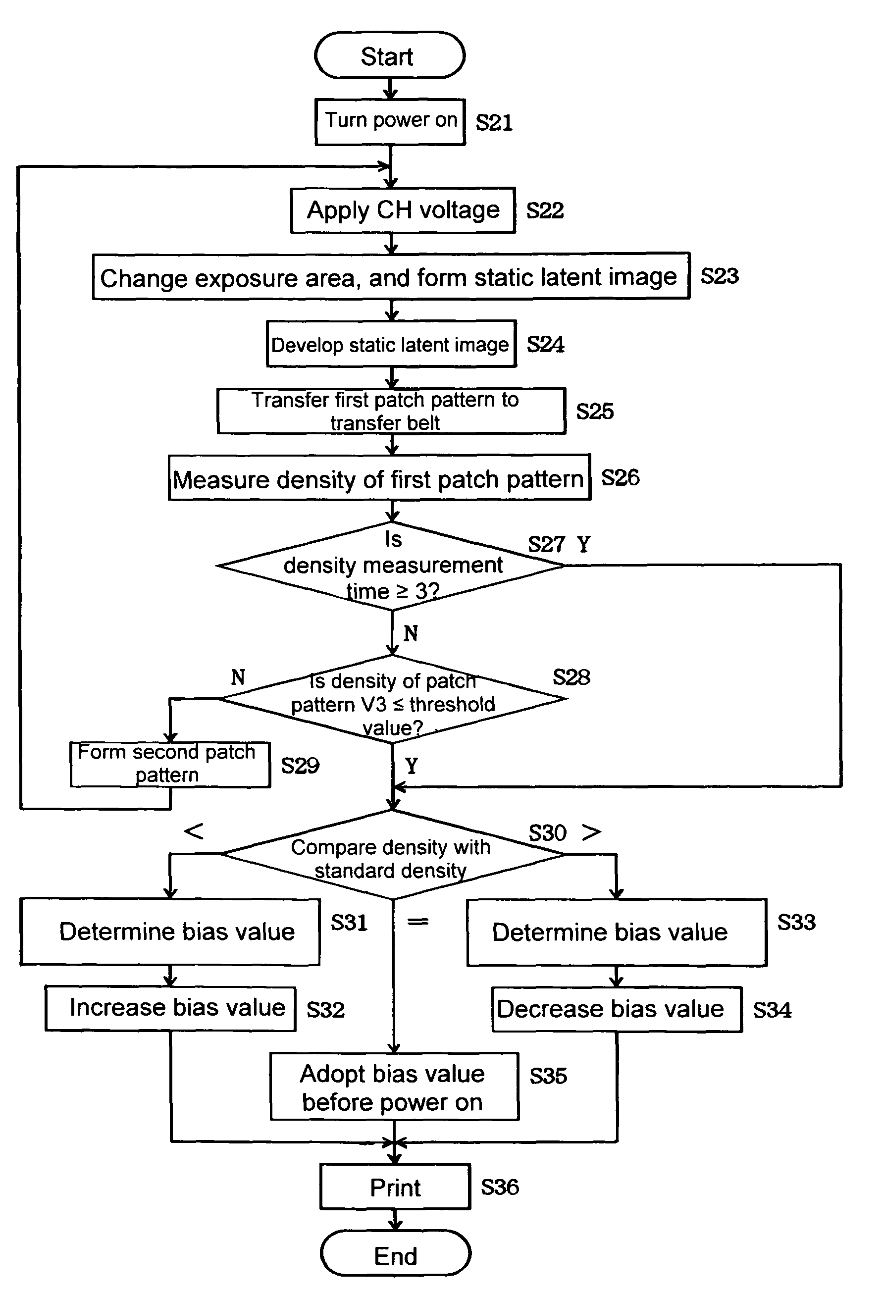
[0155]FIG. 19 is a flow chart showing an operation of the image forming apparatus 1 according to a third embodiment of the present invention. FIG. 20 is a schematic view showing a patch pattern according to the third embodiment of the present invention.

[0156]In the third embodiment, the image forming apparatus 1 has a configuration similar to that in the second embodiment, and an explanation thereof is omitted. An operation of the density correction will be explained.

[0157]When the image forming apparatus 1 is turned on, a voltage supply unit (not shown) applies a voltage to the charge roller 1...


PUM


Abstract

An image forming apparatus includes an image supporting member; an exposure device for forming a static latent image on the image supporting member; a developing device for developing the static latent image formed on the image supporting member; an image control unit for controlling a condition for forming an image; and a density sensor for detecting a developer density. In the image forming apparatus, a first pattern for detecting the developer density is formed to determine whether the developer density is proper. When the developer density thus detected is greater than a threshold value, a second pattern for discarding developer is formed to discard the developer. A third pattern for density correction is formed to perform the density correction.

Description

BACKGROUND OF THE INVENTION[0001]The present invention relates to an image forming apparatus and a method of performing density correction for the image forming apparatus.[0002]A conventional image forming apparatus performs a printing operation after density correction is performed (refer to Patent Reference).Patent Reference: Japan Patent Publication No. 2004-341100[0003]In the conventional image forming apparatus, when density abnormality occurs due to deterioration of toner after placing for a long period of time, the density correction is performed according to the density abnormality. Accordingly, when the conventional image forming apparatus performs a printing operation, image quality tends to deteriorate upon printing.[0004]In view of the problem described above, an object of the invention is to provide an image forming apparatus, in which it is possible to solve the problems of the conventional image forming apparatus. In the image forming apparatus of the present inventio...

Claims


Application Information

Patent Timeline
Patent Type & Authority Patents(United States)
IPC IPC(8): G03G15/00
CPCG03G15/0849G03G15/5041G03G15/0194G03G2215/00042G03G2215/00059G03G15/5058
Inventor TSUNODA, ARIHIRO
Owner OKI DATA CORP
Why Eureka
Try Eureka