Generating a trigger from a differential signal

a differential signal and trigger technology, applied in the direction of pulse manipulation, pulse technique, instruments, etc., can solve the problems of inconvenient triggering, trigger jit, combined trigger signal may have piecewise transition, etc., and achieve the effect of triggering test and measurement instruments that are not suitable for testing and measurement instruments

Inactive Publication Date: 2011-01-11
TEKTRONIX INC
View PDF6 Cites 6 Cited by
  • Summary
  • Abstract
  • Description
  • Claims
  • Application Information

AI Technical Summary

Problems solved by technology

However, this may result in inaccurate triggering when the differential input signal is not perfectly balanced.
This approach avoids the inaccurate triggering described above, however it only works for relatively low frequency input signals because all known methods of converting differential signals into single-ended signals either limit bandwidth or require a custom ASIC.
Hz. Furthermore, op amps inject noise onto the input signal which results in trigger jit
This approach avoids a differential-to-single-ended conversion, however the two output signals may transition at different times when the differential input signal is not perfectly balanced or when the threshold voltage level is set to other than the mid-point of the signals, and thus the combined trigger signal may have a piecewise transition which is unsuitable for triggering test and measurement instruments.

Method used


Image

  • Generating a trigger from a differential signal
  • Generating a trigger from a differential signal

Examples


Embodiment Construction

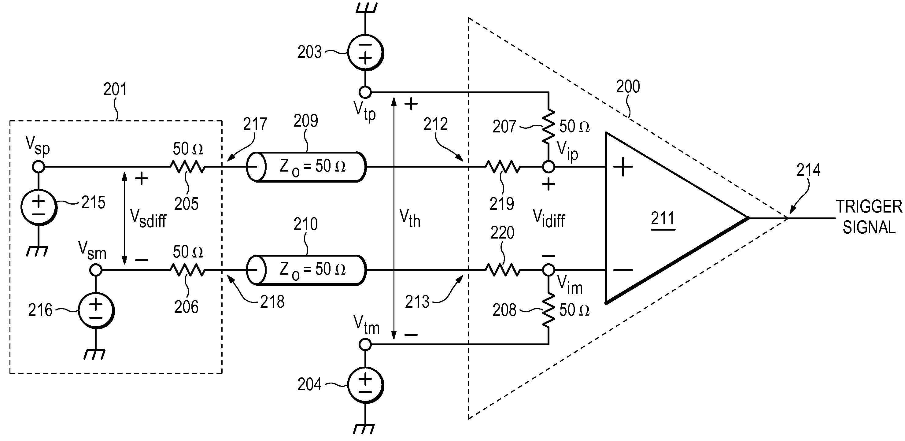
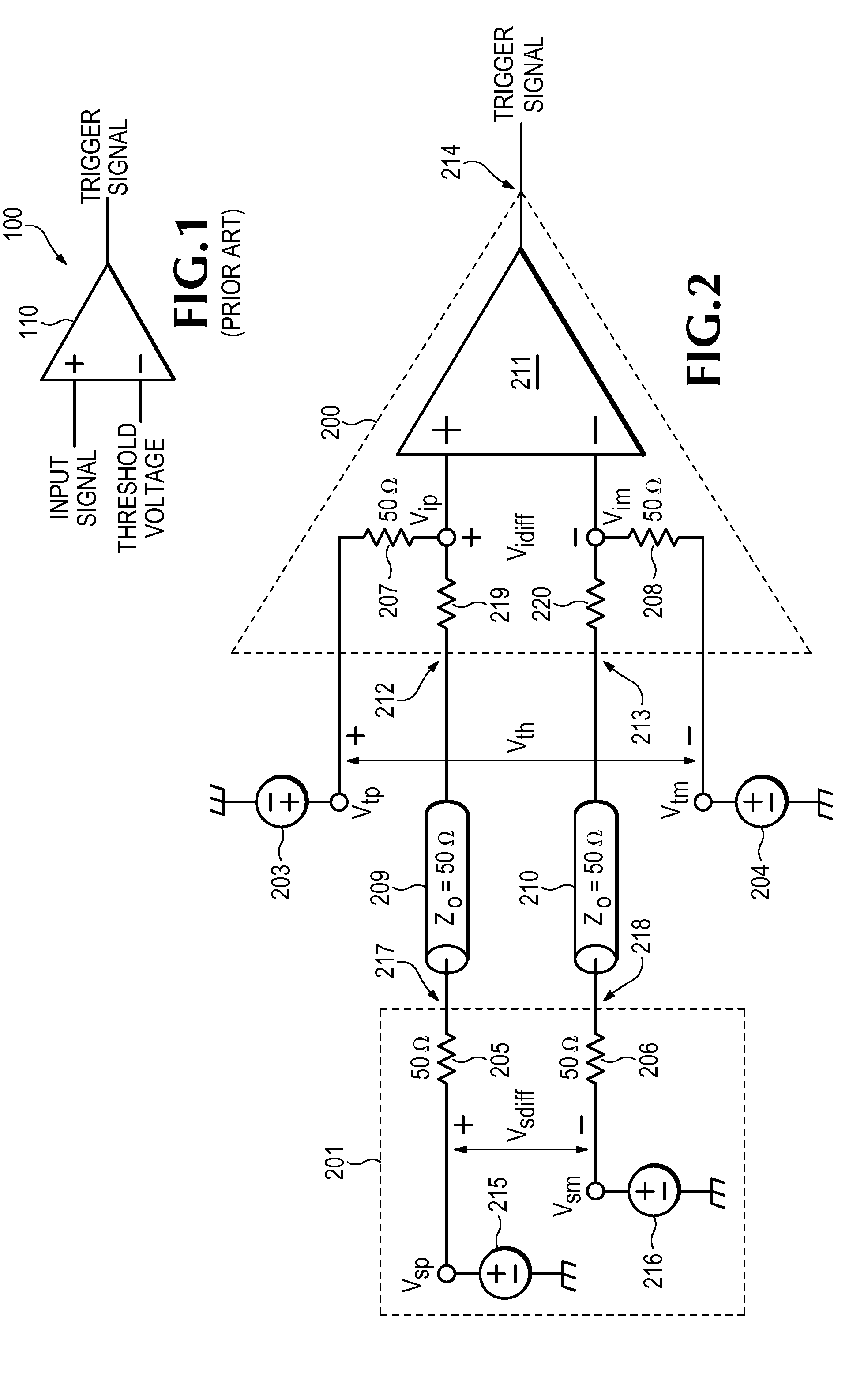
[0012]Referring now to FIG. 2, a source-terminated differential signal source 201 transmits a differential input signal Vsdiff (which consists of nominally complementary single-ended signals Vsp and Vsm) via transmission lines 209 and 210 to a trigger circuit 200 according to the present invention. Transmission lines 209 and 210 represent interconnections having a 50 ohm characteristic impedance such as coaxial cables or traces on a circuit board. Trigger circuit 200 receives a differential threshold voltage level Vth (which consists of complementary single-ended signals Vtp and Vtm) from voltage sources 203 and 204.

[0013]Differential signal source 201 contains complementary voltage sources 215 and 216. An output of voltage source 215 is coupled through a 50 ohm source termination resistor 205 to a first output terminal 217 of differential signal source 201. Similarly, an output of voltage source 216 is coupled through a 50 ohm source termination resistor 206 to a second output term...


PUM


Abstract

A trigger circuit generates a trigger signal when a differential input signal crosses a differential threshold voltage level. A first side of the differential input signal is applied to a first terminal of a first load termination resistor. A second side of the differential signal is applied to a first terminal of a second load termination resistor. A first side of the differential threshold voltage level is applied to a second terminal of the first load termination resistor. A second side of the differential threshold voltage level is applied to a second terminal of the second load termination resistor. A comparator generates the trigger signal when a voltage level at the first terminal of the first resistor exceeds a voltage level at the first terminal of the second resistor.

Description

FIELD OF THE INVENTION[0001]The present invention relates to triggers for test and measurement instruments, and more particularly to triggers for differential signals.BACKGROUND OF THE INVENTION[0002]Oscilloscopes such as the DPO / DSA70000 Series Oscilloscopes available from Tektronix, Inc. of Beaverton, Oreg. use trigger circuits to provide stable waveforms for display, quickly capture abnormal behavior, etc. One type of trigger circuit is an “edge trigger” which triggers the oscilloscope when an input signal crosses a user-specified threshold voltage level in a user-specified direction. An edge trigger is typically implemented with a comparator. For example, as shown in FIG. 1, comparator 110 generates a trigger signal when an input signal exceeds a threshold voltage level.[0003]However, input signals may not be single-ended as shown in FIG. 1, but instead may be differential. A differential signal is expressed as the difference between two complementary single-ended signals, each ...

Claims


Application Information

Patent Timeline
Patent Type & Authority Patents(United States)
IPC IPC(8): H03K5/22
CPCH03K5/00
Inventor MARKOZEN, GENE L.HICKMAN, BARTON T.
Owner TEKTRONIX INC
Why Eureka
Try Eureka