

Optical lens system for taking image
a technology of optical lens and image, applied in the field of optical lens system for taking image, can solve the problem of reducing the probability of shading, and achieve the effect of improving image quality and effectively reducing the total track length
Active Publication Date: 2011-01-11
LARGAN PRECISION
View PDF2 Cites 267 Cited by
- Summary
- Abstract
- Description
- Claims
- Application Information
AI Technical Summary
Benefits of technology
The solution effectively improves image quality, reduces the total track length, and maintains miniaturization by balancing refractive powers and correcting various aberrations, while allowing for cost-effective high-precision lens production using either glass or plastic materials, thus addressing the limitations of conventional systems.
Problems solved by technology
This also reduces the probability of the occurrence of shading.
Method used
View moreImage
Smart ImageViewing Examples

Examples
first embodiment
accordance with the present invention;
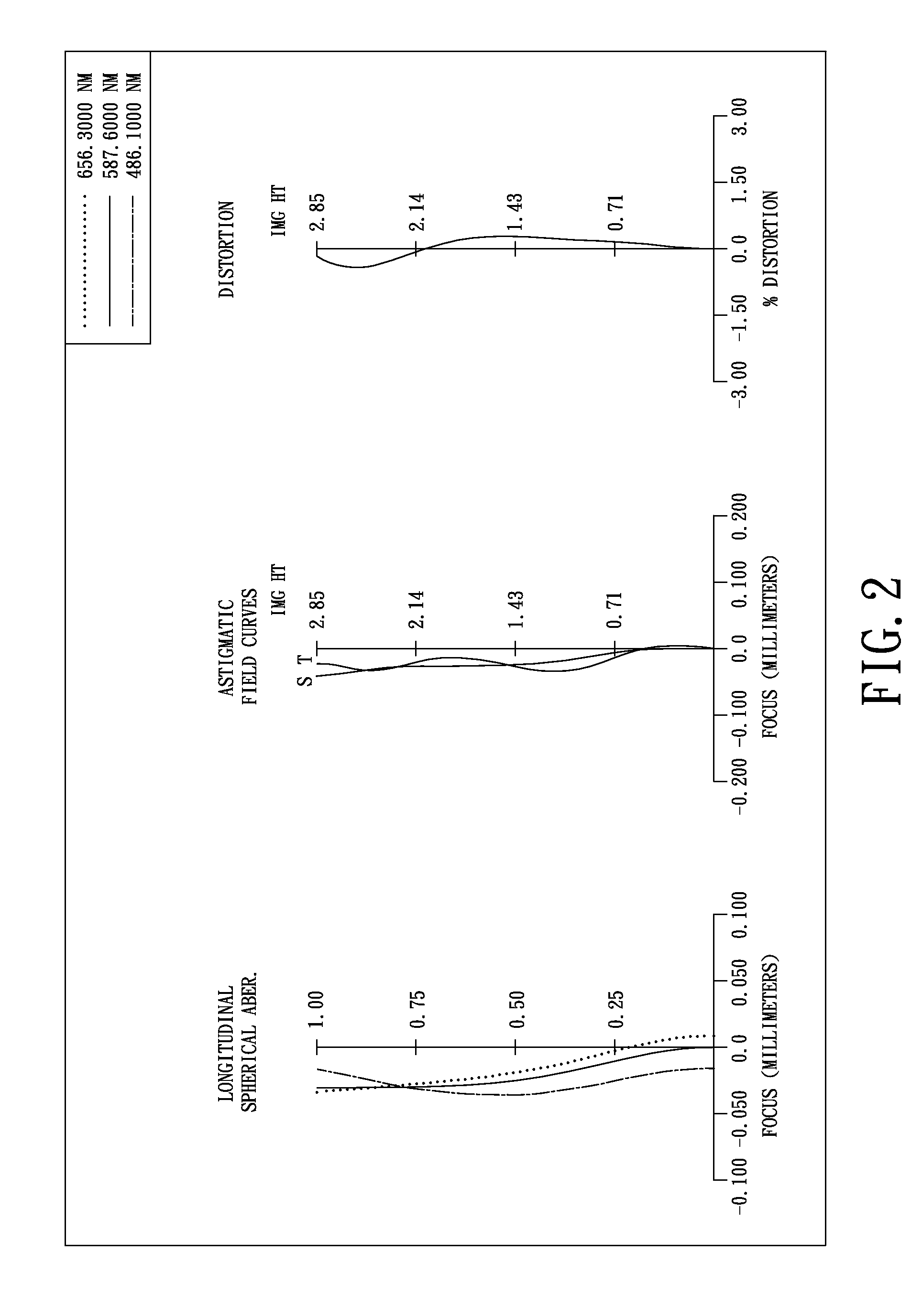
[0028]FIG. 2 shows the aberration curves of the first embodiment of the present invention;
[0029]FIG. 3 shows an optical lens system for taking image in accordance with a second embodiment of the present invention;
[0030]FIG. 4 shows the aberration curves of the second embodiment of the present invention;
[0031]FIG. 5 shows an optical lens system for taking image in accordance with a third embodiment of the present invention; and
[0032]FIG. 6 shows the aberration curves of the third embodiment of the present invention.
Login to View More PUM
 Abstract
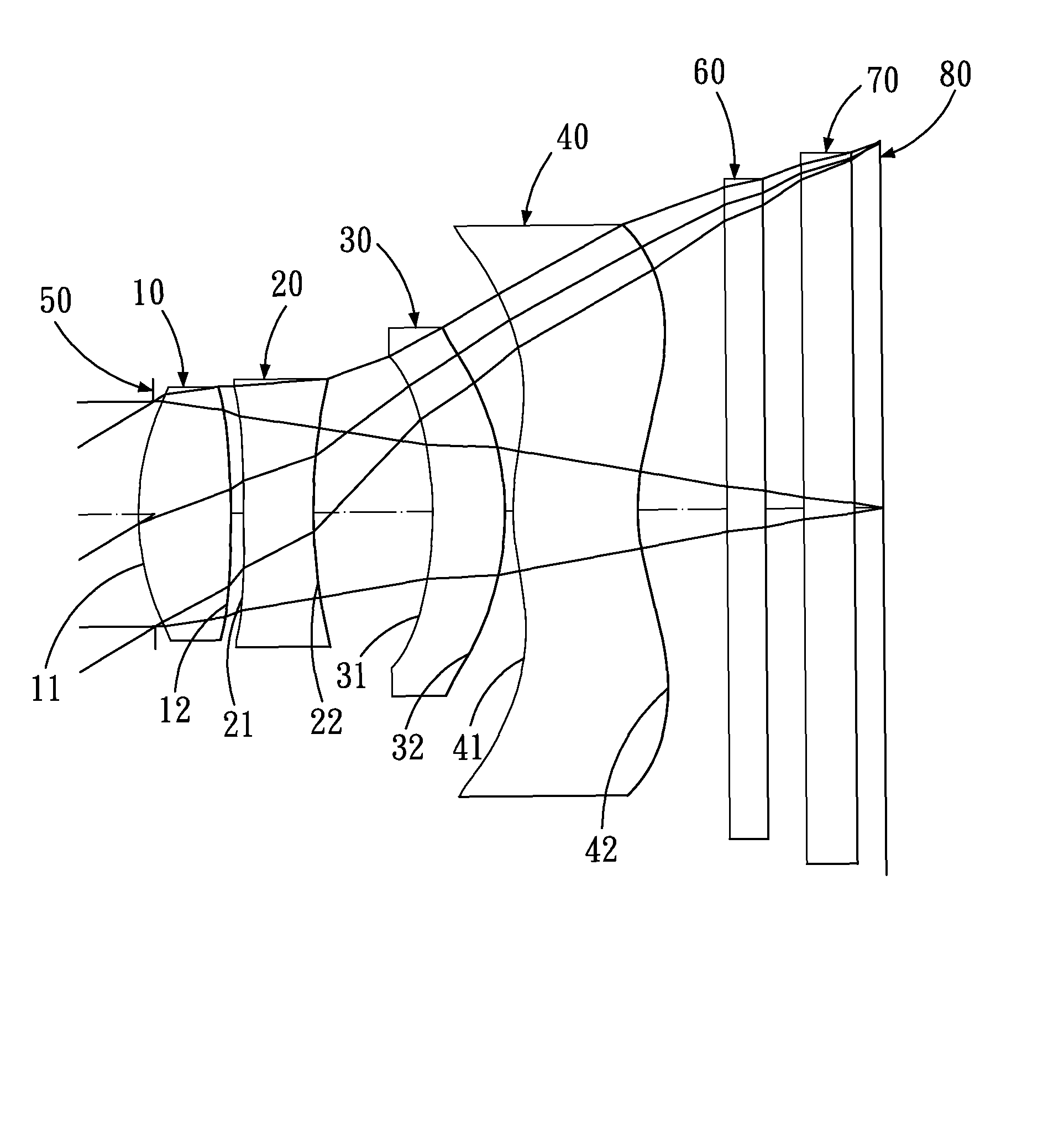
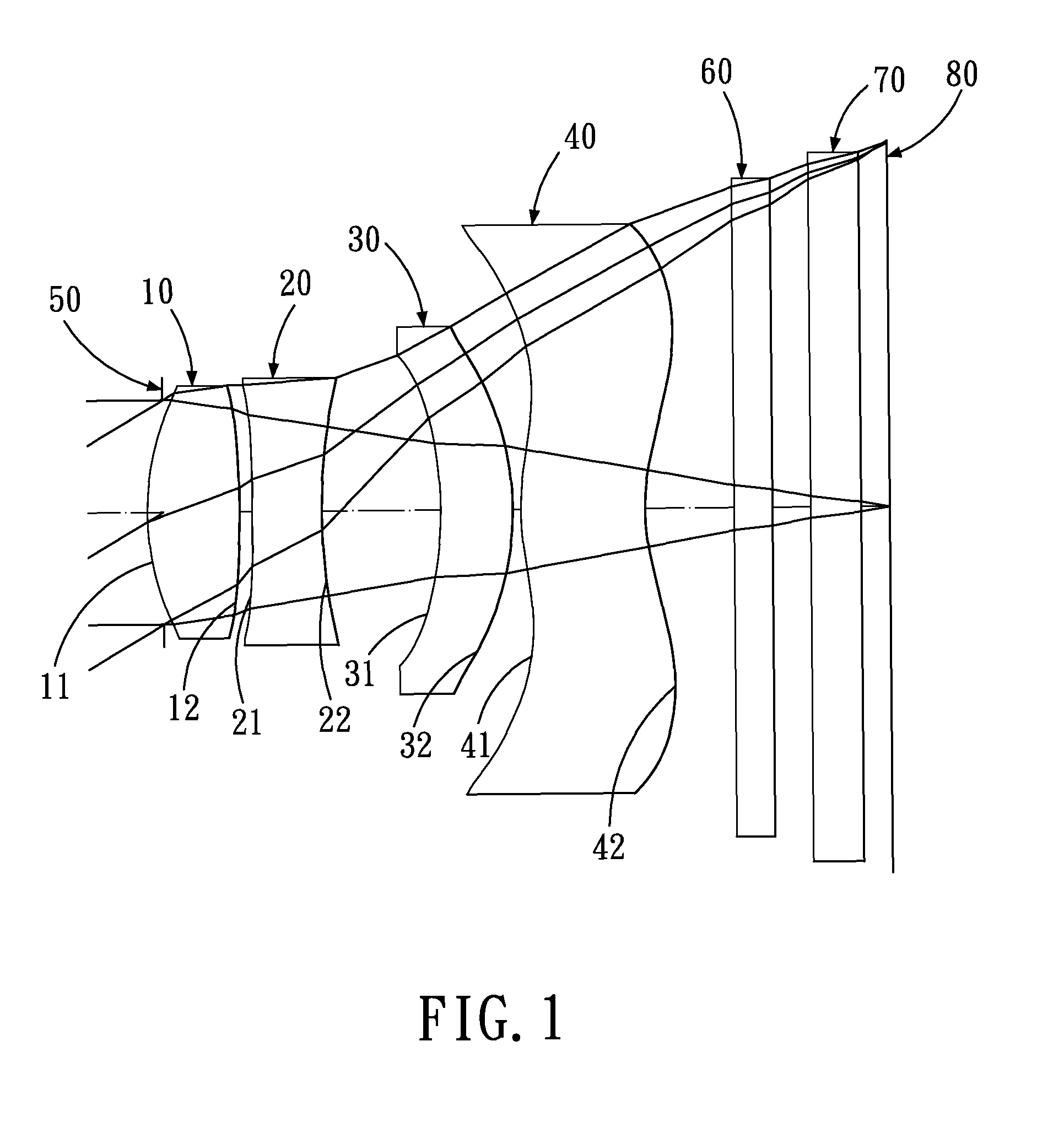
An optical lens system for taking image has, in order from the object side to the image side: a positive first lens element with a convex object-side surface; a negative plastic second lens element with a concave object-side surface; a negative plastic third lens element with a concave object-side surface; a positive fourth lens element with a concave image-side surface; and an aperture stop located between an object to be photographed and the second lens element. The second lens element is provided with at least one aspheric surface, the third lens element is provided with at least one aspheric surface, and the fourth lens element is formed with inflection points. An on-axis distance between the first and second lens elements is T12, a focal length of the optical lens system for taking image is f, they satisfy the relation: (T12 / f)*100>0.7.
Description
BACKGROUND OF THE INVENTION[0001]1. Field of the Invention[0002]The present invention relates to an optical lens system for taking image, and more particularly to a miniaturized optical lens system for taking image used in a mobile phone camera.[0003]2. Description of the Prior Art[0004]In recent years, with the popularity of the mobile phone camera, the optical lens system for taking image has become thinner and thinner, and the electronic imaging sensor of a general digital camera is typically a CCD (Charge Coupled Device) or CMOS (Complementary Metal Oxide Semiconductor) sensor. Due to advances in semiconductor manufacturing, the pixel size of sensors has been reduced continuously, and miniaturized optical lens systems for taking image have increasingly higher resolution. Therefore, there's increasing demand for image quality.[0005]A conventional mobile phone camera usually consists of three lens elements: from the object side to the image side: a first lens element with positive...
Claims
Login to View More Application Information
Patent Timeline
 Patent Type & AuthorityPatents(United States)
IPC IPC(8): G02B9/36G02B13/18G02B3/02
CPCG02B9/38G02B9/56G02B13/004
InventorCHEN, CHUN-SHANTANG, HSIANG-CHITSAI, TSUNG-HAN
OwnerLARGAN PRECISION