Corrosion evaluation device and corrosion evaluation method

a corrosion evaluation and corrosion technology, applied in the direction of instruments, magnetic properties, material magnetic variables, etc., can solve the problems of inability to perform quantitative evaluation of corrosion, etc., to achieve the effect of higher magnetic sensitivity

Active Publication Date: 2011-05-17
IHI CORP
View PDF10 Cites 1 Cited by
  • Summary
  • Abstract
  • Description
  • Claims
  • Application Information

AI Technical Summary

Benefits of technology

[0015]According to the present invention, by using a GMR sensor having higher magnetic sensitivity than a magnetic sensor using a hall element, even if a magnetic material which is to be evaluated is covered by a non magnetic material, it is possible to precisely detect a leak magnetic flux. As a result, it is possible to precisely calculate a quantity of decrease in the thickness of a magnetic material such as a reinforcing steel or a steel plate or the like, it is possible to precisely perform quantitative evaluation of corrosion.

Problems solved by technology

Now, in the magnetic flux leakage method that used a hall element as a magnetic sensor, because magnetic sensitivity of the hall element is weak, when the steel material, which is an object to be evaluated, is covered by a non magnetic material such as concrete or the like, it was not possible to precisely detect the magnetic flux leakage and so it was difficult to perform quantitative evaluation of corrosion.
That is, a ruptured portion of the steel material covered by a non magnetic material such as concrete or the like can be detected, but it is not possible to perform quantitative evaluation of corrosion.
However, these methods can determine the presence of corrosion, but quantitative evaluation cannot be performed.

Method used


Image

  • Corrosion evaluation device and corrosion evaluation method
  • Corrosion evaluation device and corrosion evaluation method
  • Corrosion evaluation device and corrosion evaluation method

Examples


application example 1

[0052]FIG. 8 shows an application example of the corrosion evaluation device D. As shown in FIG. 8, the corrosion evaluation device D is disposed in the bogie 10 which is able to move itself by program control. The bogie 10 moves two-dimensionally along the concrete C which covers the reinforcing steel S and measures the quantity of decrease in the thickness at each of the predetermined measurement points. The quantity of decrease in the thickness measured at each of the measurement points is stored in the data recorder 8 one by one. In order to maintain the detection accuracy of the magnetic flux leakage, it is preferable to maintain a constant distance between the surface of the reinforcing steel S and the GMR sensor 3 (measurement gap). However, the surface of the concrete C is not always horizontal in accordance with measurement points on the surface of the concrete C. Accordingly, the bogie 10 has a function to compensate for the measurement gap at each of the measurement point...

application example 2

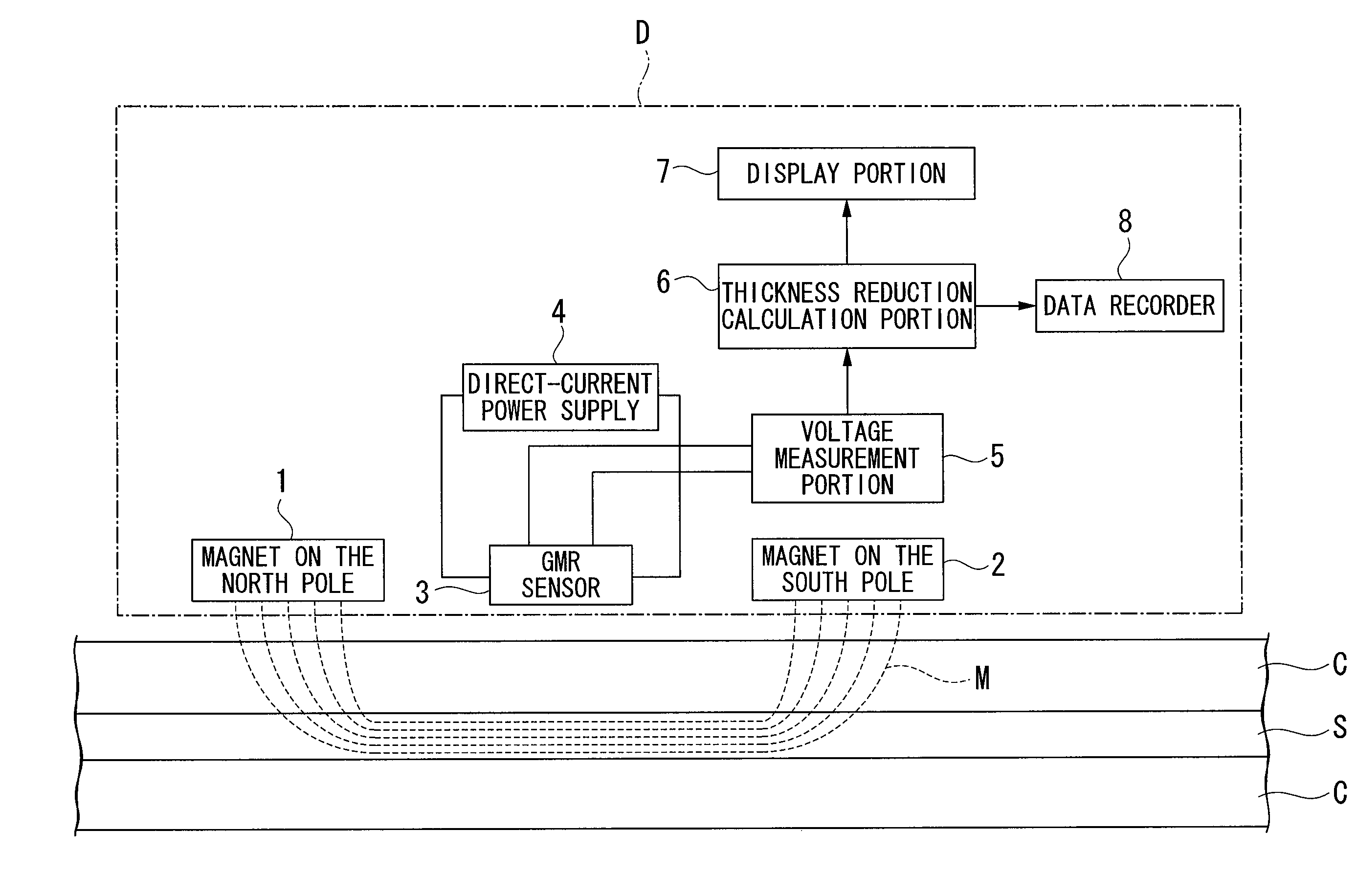
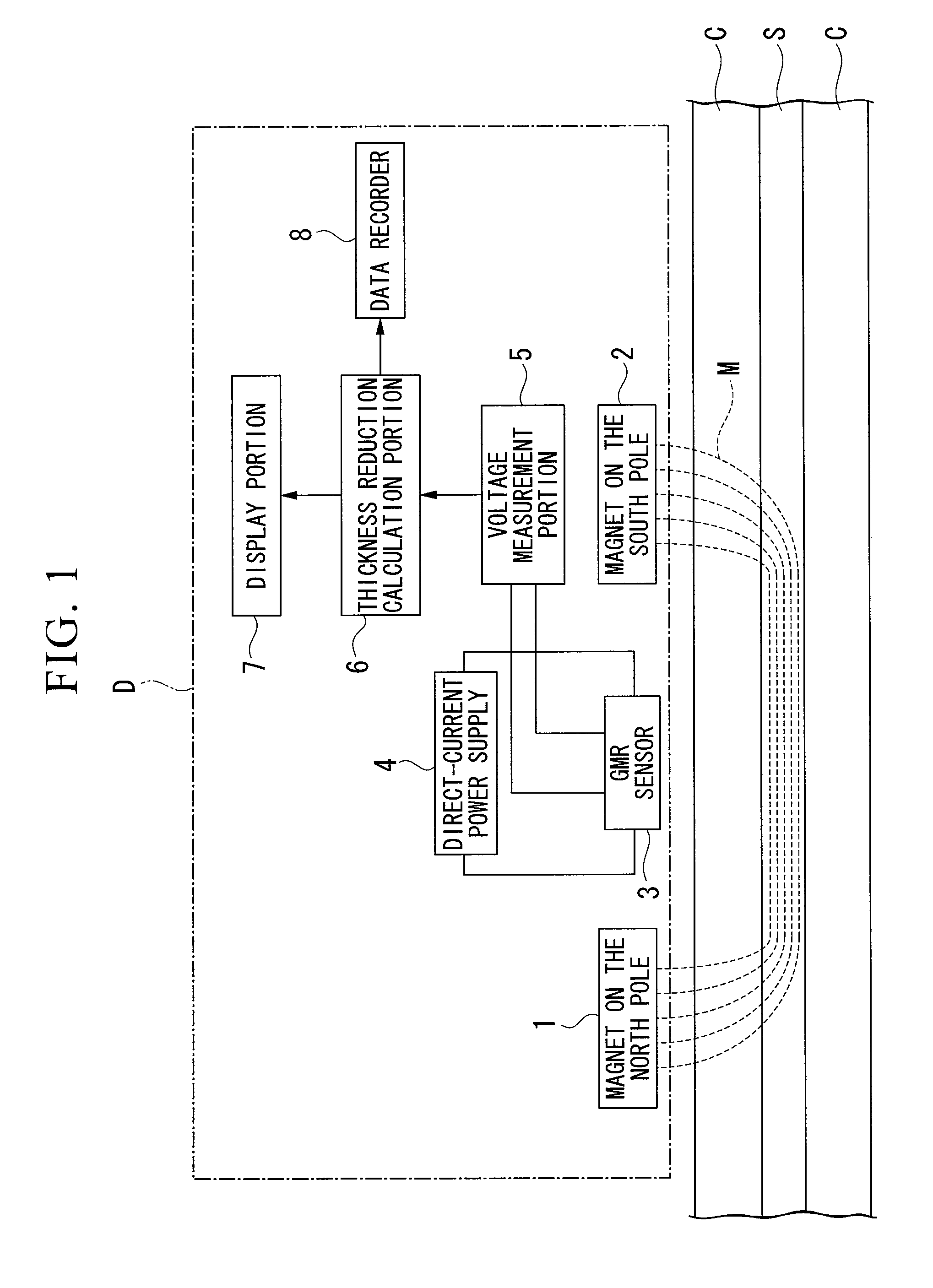
[0054]FIG. 9 shows an application example 2 of the corrosion evaluation device D. As shown in FIG. 9, the corrosion evaluation device D of the application example 2 has a probe 20 provided with the magnet 1 on the north pole, the magnet 2 on the south pole, and the GMR sensor 3, and an operation box 22 connected via the probe 20 and a cable 21 provided with the direct-current power supply 4, a voltage measurement portion 5, the thickness reduction calculation portion 6, the display portion 7, and the data recorder 8. An operator 30 moves the probe 20 which is held in one hand to a preferred measurement point along the surface of the concrete C which covers the reinforcing steel S. At this time, the operator visually confirms the quantity of decrease in the thickness which is displayed on the display portion 7 of the operation box 22 and can recognize the progress of corrosion if any.

[0055]In accordance with the application example 2 as described above, it is possible to effectively ...


PUM


Abstract

A corrosion evaluation device for performing a quantitative evaluation of corrosion by measuring a quantity of decrease in the thickness of a magnetic material which is covered by a non magnetic material or a magnetic material which is not covered by a non magnetic material which includes: a magnetic field generating device for generating such a magnetic field that includes the magnetic material in a magnetic path, a Giant Magnet-Resistive effect (GMR) sensor provided with a GMR sensor for detecting a magnetic flux leakage with regard to the magnetic material and converts a change in the magnetic flux into an electrical signal, a thickness reduction calculation portion for calculating a quantity of decrease in the thickness of the magnetic material based on the electrical signal. The corrosion evaluation device precisely performs a quantitative evaluation of corrosion even when the magnetic material, which is to be evaluated, is covered by a non magnetic material.

Description

CROSS REFERENCE TO RELATED APPLICATIONS[0001]The present application is a 35 U.S.C. §371 National Phase conversion of PCT / JP2006 / 325172, filed Dec. 18, 2006, which claims priority of Japanese Application No. 2005-364387, filed Dec. 19, 2005, and Japanese Application No. 2006-309165, filed Nov. 15, 2006, the disclosures of which have been incorporated herein by reference. The PCT International Application was published in the Japanese language.TECHNICAL FIELD[0002]The present invention relates to a corrosion evaluation device and a corrosion evaluation method.BACKGROUND ART[0003]A Magnetic Flux Leakage Method (MFL), which measures quantity of decrease in the thickness of the steel material by adding a magnetic field to the steel material and detecting a change of magnetic flux leakage, has been conventionally used as one of the methods to quantitatively evaluate the progress of corrosion in steel material (magnetic material) which are used for pipelines of oil or gas, a bottom plate ...

Claims


Application Information

Patent Timeline
Patent Type & Authority Patents(United States)
IPC IPC(8): G01R33/02
CPCG01N27/83G01N17/006G01R33/12G01R33/091
Inventor HATANAKA, HIROAKITODA, KATSUYATAGAMI, MINORU
Owner IHI CORP
Why Eureka
Try Eureka