External heat dissipation device

a heat dissipation device and external technology, applied in the direction of lighting, heating apparatus, electric apparatus casings/cabinets/drawers, etc., can solve the problems of unsuitable installation of a larger thermal module inside the portable electronic device, and the generation of large amounts of hea

Inactive Publication Date: 2011-05-24
HON HAI PRECISION IND CO LTD
View PDF37 Cites 8 Cited by
  • Summary
  • Abstract
  • Description
  • Claims
  • Application Information

AI Technical Summary

Benefits of technology

[0004]At present, a thermal module is generally mounted on a central processing unit (CPU) inside a portable electronic device, such as a portable computer, causing heat generated by the CPU to be dissipated into the surrounding air. However, with the ever increasing integration density of CPUs, greater amounts of heat are being generated, requiring larger thermal modules for quickly and efficiently removing heat.

Problems solved by technology

However, with the ever increasing integration density of CPUs, greater amounts of heat are being generated, requiring larger thermal modules for quickly and efficiently removing heat.
However, portable electronic devices are often designed to be compact for high portability.
When trying to create small-sized portable electronic devices, the installation of a larger thermal module inside the portable electronic devices is un-desirable.

Method used


Image

  • External heat dissipation device
  • External heat dissipation device
  • External heat dissipation device

Examples


Embodiment Construction

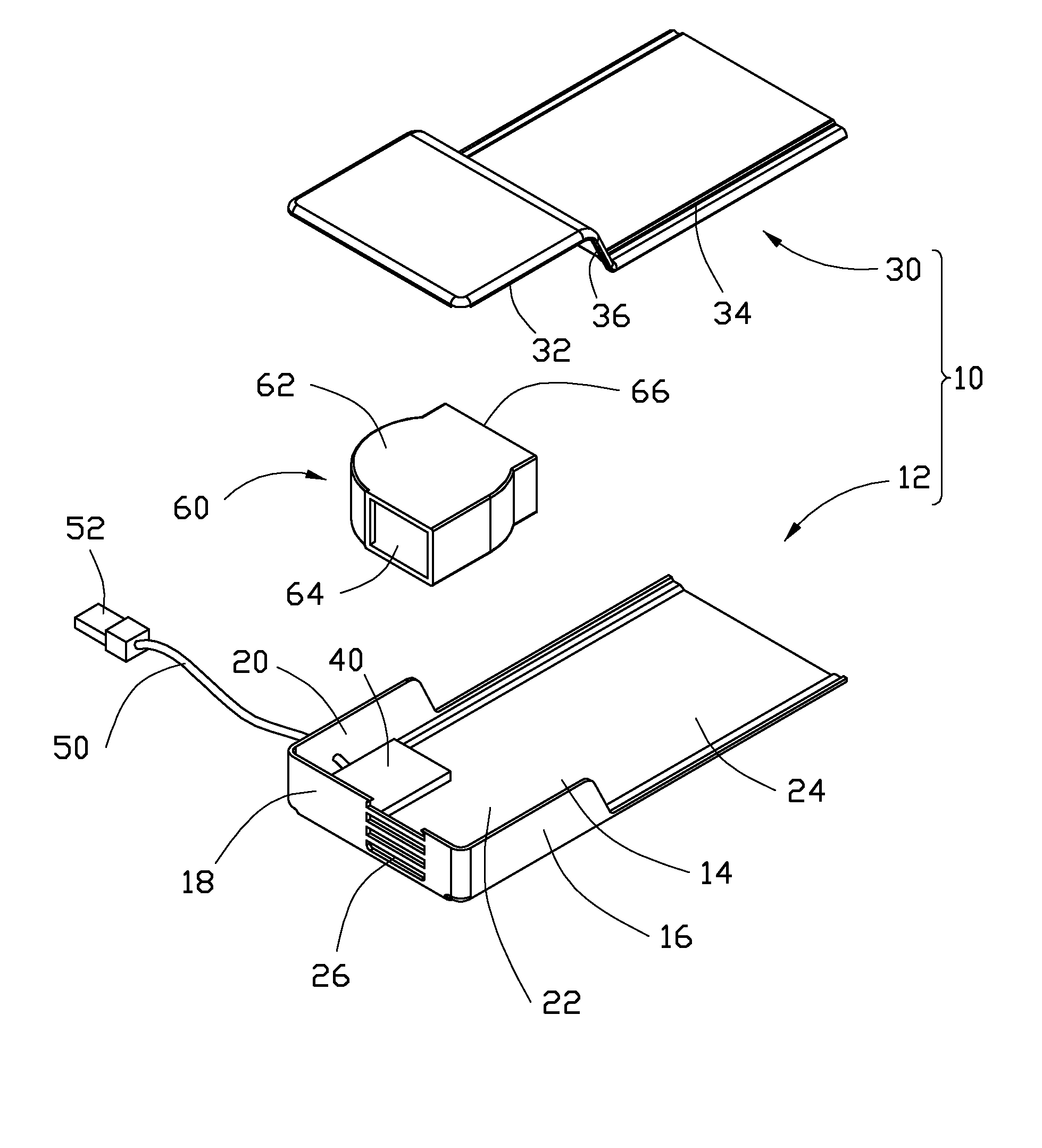
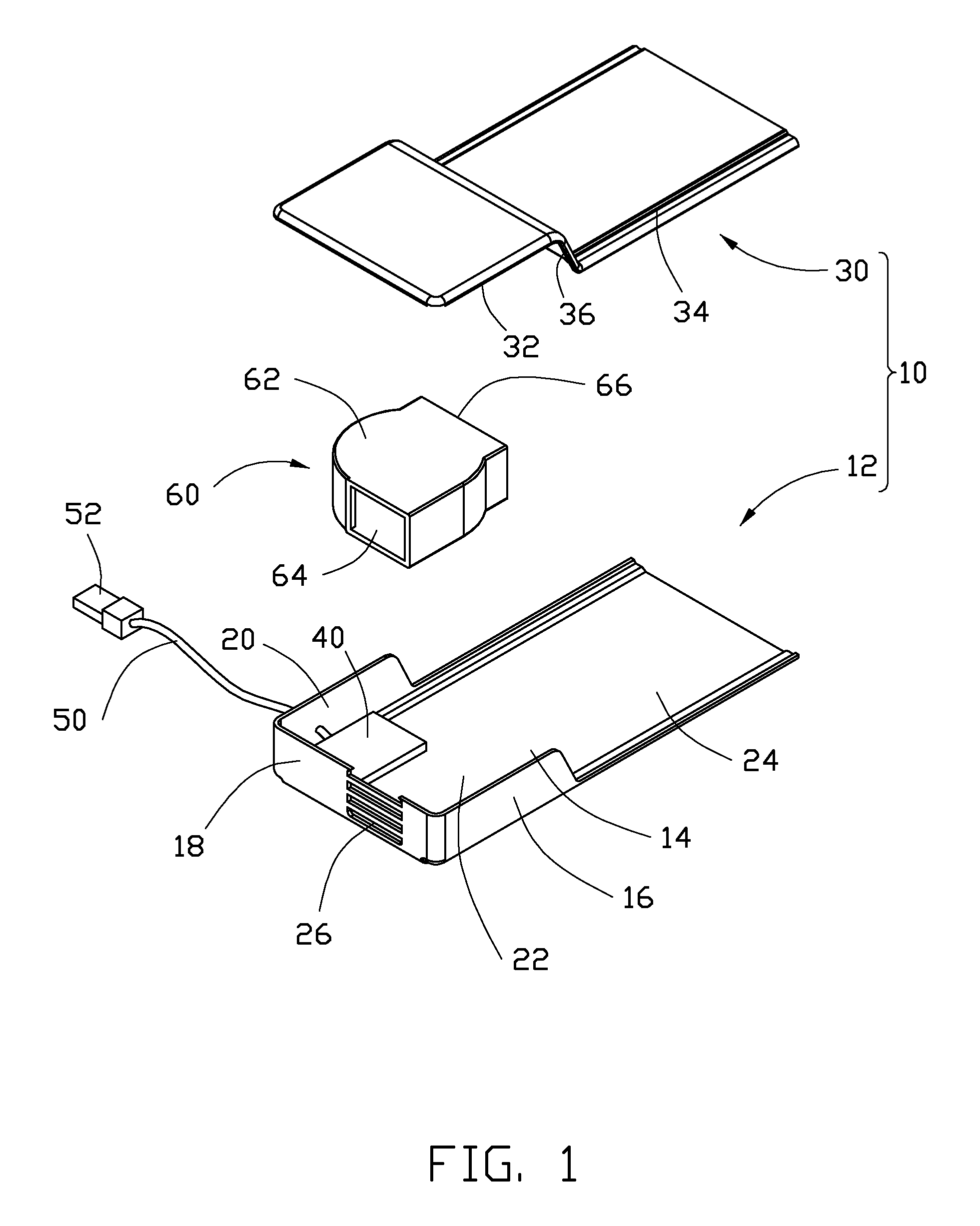
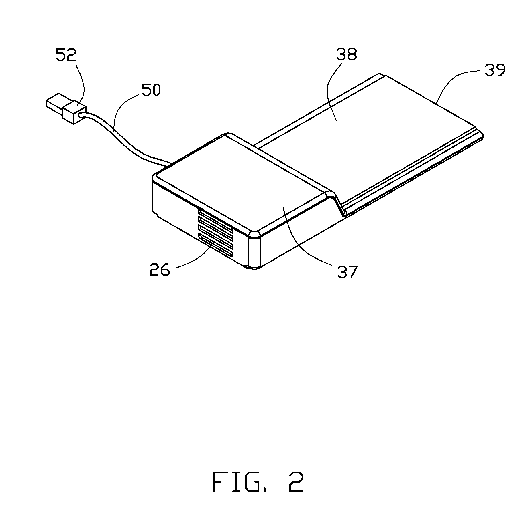
[0009]Referring to FIG. 1, an exemplary embodiment of an external heat dissipation device includes a housing 10, a circuit board 40, a wire 50 electrically connected to the circuit board 40, and a fan 60.

[0010]The housing 10 includes an elongated base 12 and an elongated cover 30. The base 12 includes a panel 14. A generally U-shaped surrounding plate 20 extends from a first end of the panel 14. The surrounding plate 20 includes two opposite first walls 16 perpendicularly extending up from opposite sides of the panel 14, adjacent to the first end of the panel 14, and a second wall 18 perpendicularly connected between the first walls 16. The panel 14 and the first and second walls 16 and 18 together define a receiving space 22. An extension portion 24 extends from and is coplanar to a second end of the panel 14 opposite to the first end thereof. A plurality of air intakes 26 are defined in the second wall 18. The cover 30 includes a first coupling plate 32 for overlapping a top of th...


PUM


Abstract

An external heat dissipation device includes a housing, a circuit board placed in the housing, a fan electrically connected to the circuit board, and a wire electrically connected to the circuit board to power the fan. The housing includes an installation dock defining a receiving space for receiving the fan therein, and an insertion portion extending from the installation dock. A through hole is defined in the installation dock. An air passage is defined in the insertion portion. The fan includes a casing defining a first air hole communicating with the through hole and a second air hole communicating with the air passage.

Description

BACKGROUND[0001]1. Technical Field[0002]The disclosure relates to heat dissipation devices, and particularly, to an external heat dissipation device for a portable electronic device.[0003]2. Description of Related Art[0004]At present, a thermal module is generally mounted on a central processing unit (CPU) inside a portable electronic device, such as a portable computer, causing heat generated by the CPU to be dissipated into the surrounding air. However, with the ever increasing integration density of CPUs, greater amounts of heat are being generated, requiring larger thermal modules for quickly and efficiently removing heat.[0005]However, portable electronic devices are often designed to be compact for high portability. When trying to create small-sized portable electronic devices, the installation of a larger thermal module inside the portable electronic devices is un-desirable.BRIEF DESCRIPTION OF THE DRAWINGS[0006]FIG. 1 is an exploded, isometric view of an exemplary embodiment...

Claims


Application Information

Patent Timeline
Patent Type & Authority Patents(United States)
IPC IPC(8): H05K7/20G06F1/16
CPCG06F1/203
Inventor HUANG, CHI-SHIH
Owner HON HAI PRECISION IND CO LTD
Why Eureka
Try Eureka