Fuel cell assembly manifold heater for improved water removal and freeze start

a fuel cell and manifold heater technology, which is applied in the direction of fuel cells, cell components, fuel cell groupings, etc., can solve the problems of limiting the flow of fluid through the outlet manifold, damage to the fuel cell assembly, and condensation may form ice, so as to achieve quick and efficient heating of the fuel cell assembly

Active Publication Date: 2013-12-10
GM GLOBAL TECH OPERATIONS LLC
View PDF10 Cites 0 Cited by
  • Summary
  • Abstract
  • Description
  • Claims
  • Application Information

AI Technical Summary

Benefits of technology

[0007]Concordant and congruous with the present invention, an apparatus for quickly and efficiently heating the fuel cell assembly to militate against ice blockage during system start-up in subfreezing temperatures to militate against water condensation accumulation at the outlet manifolds of the fuel cell assembly to militate against water condensation accumulation at the outlet manifolds of the fuel cell assembly and to militate against a subsequent formation of ice in the fuel cell assembly, has surprisingly been discovered.

Problems solved by technology

Further, the condensate may form ice in the fuel cell assembly.
The presence of condensate and ice may affect the performance of the fuel cell assembly and may also cause damage to the fuel cell assembly.
However, during typical operation conditions, condensate may accumulate at the edges of the fuel cell plates adjacent outlet manifolds thereof, thereby restricting fluid flow from the flow channels through the outlet manifolds.
During a starting operation of the fuel cell assembly in subzero temperatures, the condensed water in the flow channels of the fuel cell plates and at edges of the outlet manifolds is in the form of ice within the fuel cell assembly which may result in damage to the fuel cell assembly as reactant flow is restricted.
Similarly reactant flow maldistribution due to liquid water stagnation during normal operation can result in damage and instability.
However, increasing the operation temperature may have a negative impact on ohmic resistance due to membrane proton resistance as a result of decreased membrane humidification.
Also, decreasing the inlet relative humidity of anode and cathode gas streams will achieve the same effect as increasing temperature and may also have have a negative impact on ohmic resistance due to membrane proton resistance.

Method used


Image

  • Fuel cell assembly manifold heater for improved water removal and freeze start
  • Fuel cell assembly manifold heater for improved water removal and freeze start
  • Fuel cell assembly manifold heater for improved water removal and freeze start

Examples


first embodiment

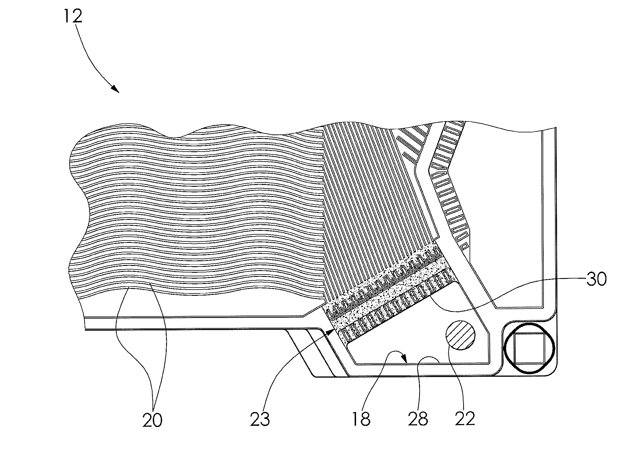
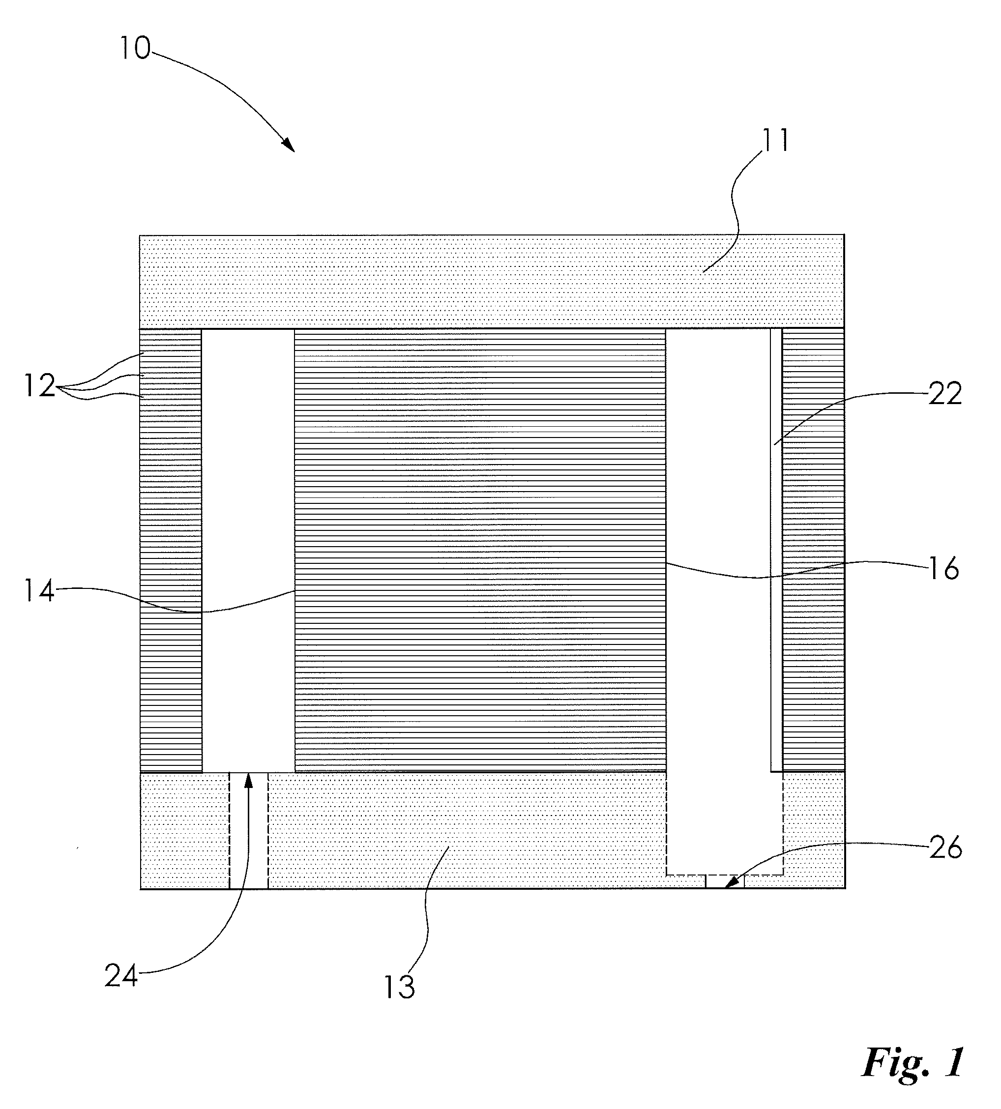
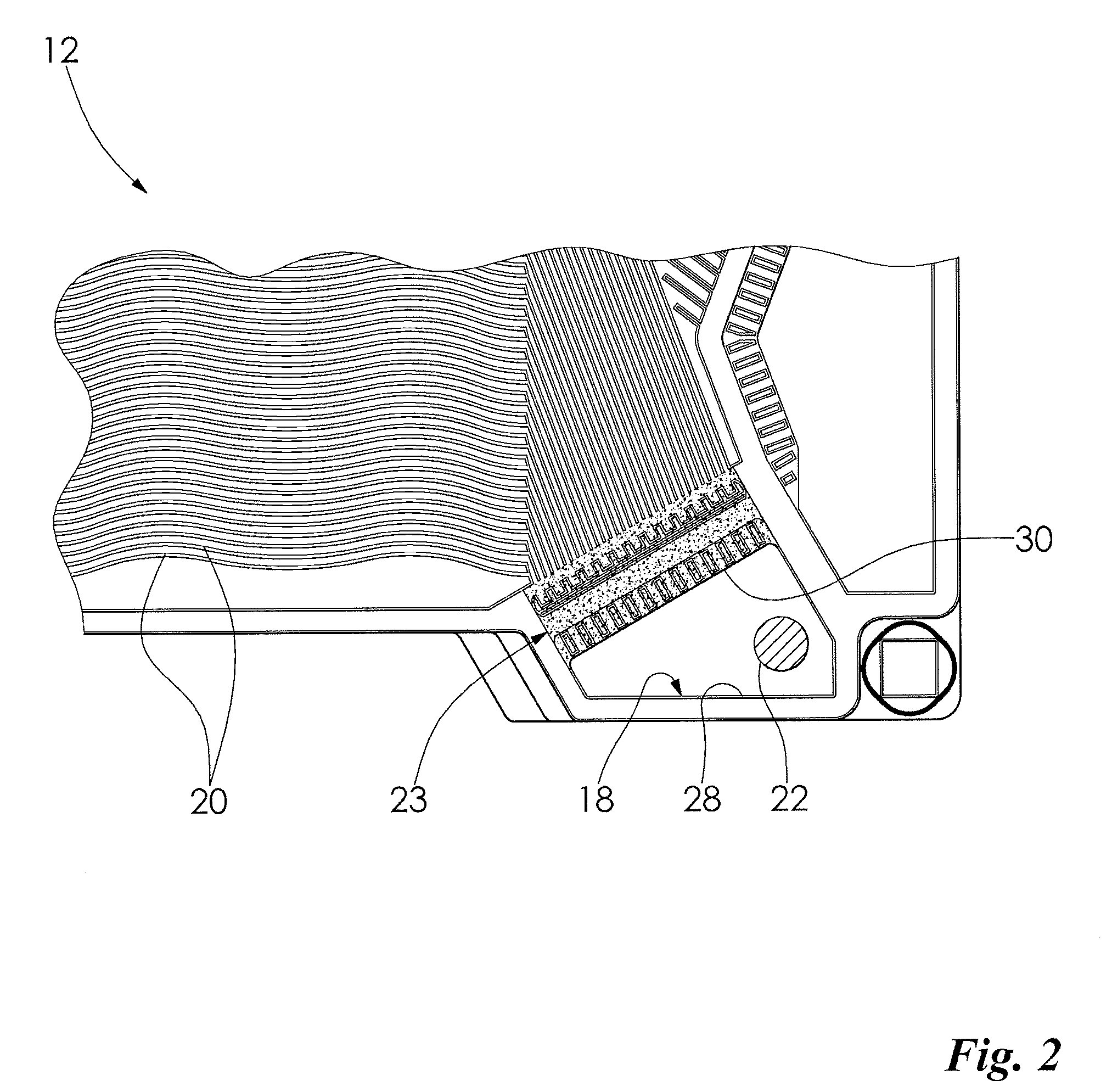
[0026]When the invention is in operation, the above reactions take place within the fuel cell assembly 10, and droplets of liquid water are formed in the channels 20 of the fuel cell plates 12 on the cathode sides of the fuel cell assembly 10. Some water also may be transported into the anode flow channels, or may form in the anode channels via condensation resulting from consumption of the hydrogen. It is understood that the operation as described herein for the cathode side is similar to operation for the anode side of the fuel cell assembly 10. The air stream flowing through the cathode side causes the water droplets to flow through the channels 20, toward the outlet manifold 16. Water vapor also flows towards the outlet manifold 16. The hydrophilic portion 23 is adapted to provide a capillary path from the flow channels 20 to the outlet manifold 16 and to facilitate a wicking of the water away from the flow channels 20.

[0027]To militate against the water droplets and vapor cond...

second embodiment

[0038]When the invention is in operation, the above reactions take place within the fuel cell assembly 10′, and droplets of liquid water are formed in the channels 20′ of the fuel cell plates 12′ on the cathode sides of the fuel cell assembly 10′. Some water also may be transported into the anode flow channels, or may form in the anode channels via condensation resulting from consumption of the hydrogen. It is understood that the operation as described herein for the cathode side is similar to operation for the anode side of the fuel cell assembly 10′. The air stream flowing through the cathode side causes the water droplets to flow through the channels 20′, toward the outlet manifold 16′. Water vapor is also caused to flow towards the outlet manifold 16′.

[0039]To militate against the water droplets and vapor condensing and collecting at the edge 30′ of the outlet aperture 18′, the means for heating 22′ is caused to heat the edge 30′ of the fuel cell plates 12′ with conductive heat...


PUM

PropertyMeasurementUnit
hydrophilicaaaaaaaaaa
stabilityaaaaaaaaaa
temperaturesaaaaaaaaaa

Abstract

An apparatus for heating a fuel cell assembly is disclosed, wherein a means for heating is disposed in a manifold of the fuel cell assembly and the means for heating causes the manifold to be heated to militate against fluid condensation and ice formation in the fuel cell assembly.

Description

FIELD OF THE INVENTION[0001]The invention relates to an apparatus for heating a fuel cell assembly, and more specifically to an apparatus for heating a manifold of the fuel cell assembly to militate against a fluid condensation and an ice formation in the fuel cell assembly.BACKGROUND OF THE INVENTION[0002]Fuel cell assemblies convert a fuel and an oxidant to electricity. One type of fuel cell power system employs use of a proton exchange membrane (hereinafter “PEM”) to facilitate catalytic reaction of fuels (such as hydrogen) and oxidants (such as air or oxygen) to generate electricity. The PEM is a solid polymer electrolyte membrane that facilitates transfer of protons from an anode to a cathode in each individual fuel cell normally deployed in a fuel cell power system.[0003]In a typical fuel cell assembly (or stack) within a fuel cell power system, individual fuel cell plates include channels through which various reactants and cooling fluids flow. Fuel cell plates are typically ...

Claims


Application Information

Patent Timeline
Patent Type & Authority Patents(United States)
IPC IPC(8): H01M8/04H01M8/24
CPCH01M8/0228H01M8/0267H01M8/04037H01M2008/1095Y02E60/50H01M8/241H01M8/2483H01M8/0258
Inventor OWEJAN, JON P.
Owner GM GLOBAL TECH OPERATIONS LLC
Why Eureka
Try Eureka