Adjustable advance distributor

a distributor and advance technology, applied in the field of distributors, can solve the problems of time-consuming and labor-intensive conventional timing adjustment, and achieve the effects of quick and easy adjustment of vehicle timing, easy turning, and added level of adjustment control

Active Publication Date: 2012-02-14
FARRELL KENNETH WILLIAM
View PDF18 Cites 4 Cited by
  • Summary
  • Abstract
  • Description
  • Claims
  • Application Information

AI Technical Summary

Benefits of technology

[0007]For these reasons, a modular and adjustable distributor assembly is desired. The distributor preferably allows a user to quickly and easily adjust the timing of the vehicle. In some configurations, the adjustable advance distributor can be adjusted without the use of mechanical tools of any type. In such embodiments, the timing can be adjusted through finger-adjustable control members. An upper housing of the distributor can be split into two separate components that are connected together by an adjustable mechanism. The adjustable mechanism allows the ignition advance to be adjusted by turning a knob. The knob forms a portion of an adjustment mechanism that connects the two separate components together. Thus, because the knob can be easily turned while the engine is running, the adjustable advance distributor can be used to make changes to the ignition timing without the use of a timing light or the like. Preferably, the housing comprises scaled degree markings for easy viewing of changes, which provides an added level of adjustment control to the user.
[0008]In some configurations, the adjustable advance distributor comprises a modular construction that allows a manufacturer to mass produce an upper adjustable portion of the distributor while facilitating an interchange of shafts to fit various engines with minimal tooling expense.

Problems solved by technology

Conventional timing adjustment could take considerable time because the distributor often moved in an unpredictable manner during tightening of the clamp nut.

Method used


Image

  • Adjustable advance distributor
  • Adjustable advance distributor
  • Adjustable advance distributor

Examples


Embodiment Construction

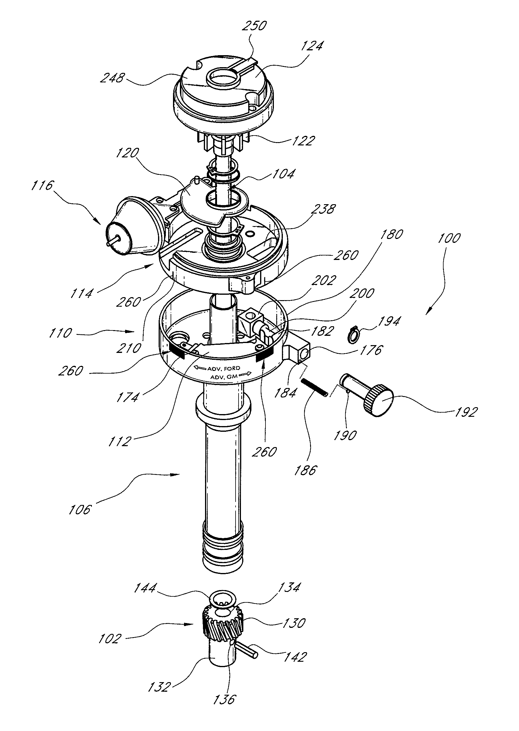
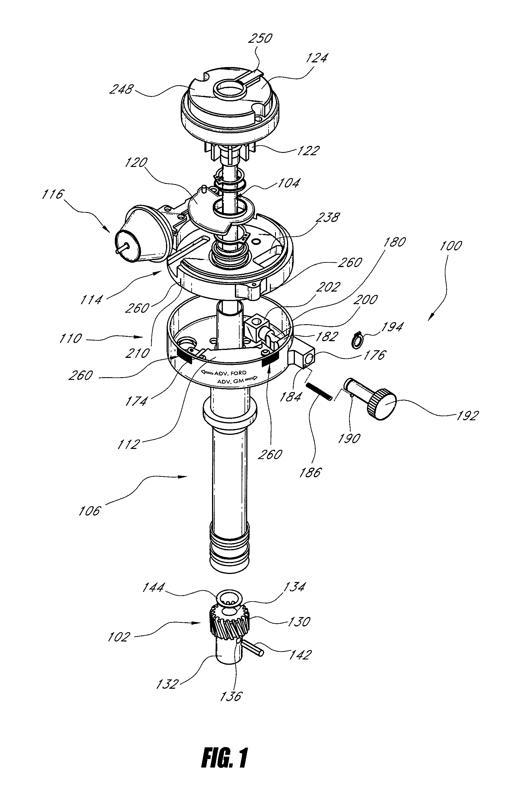
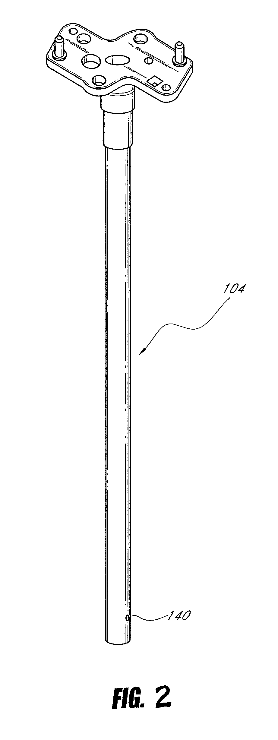
[0015]An adjustable advance distributor 100 is shown in FIG. 1. The distributor 100 generally comprises a drive gear 102. The drive gear 102 is connected to a distributor shaft 104. The distributor shaft 104 can be a hardened steel shaft having a diameter of about 0.50 inch. The distributor shaft 104 extends upward from the drive gear 102 through a shaft housing assembly 106. The shaft housing 106 connects to a lower housing assembly 110 that contains an ignition module 112 in the illustrated configuration. The lower housing assembly 110 can comprise an anodized lower housing assembly 110. A top plate assembly 114 overlies the lower housing assembly 110. The top plate assembly 114 contains at least a portion of a vacuum advance assembly 116 that connects to a cam plate 120. A timing wheel or reluctor 122 connects to the distributor shaft 104 and the distributor shaft 104 connects to a rotor assembly 124.

[0016]With reference to FIG. 1, the drive gear 102 comprises a spiral or helical...


PUM


Abstract

A distributor is configured with an outer housing that has a first portion and a second portion. The first portion and the second portion are adjustable in angular orientation relative to each other. Movement of the second portion relative to the first portion changes ignition timing in the distributor. The movement can be caused by rotation of a thumbwheel such that ignition timing can be changed without mechanical tools. The first and second portions also can comprise visual or tactile markings such that ignition timing can be changed without a timing light. The outer housing can be used in multiple applications simply by changing a length of a shaft housing member that houses a distributor shaft and a gear that is mounted to the distributor shaft.

Description

CROSS-REFERENCE TO RELATED APPLICATIONS[0001]This application is a non-provisional of U.S. Provisional Patent Application No. 61 / 099,164, which was filed on Sep. 22, 2008, claims priority to that application under 35 U.S.C. §119(e) and incorporates by reference that application in its entirety.BACKGROUND OF THE INVENTION[0002]1. Field of the Invention[0003]The present invention generally relates to distributors used to control ignition timing in motor vehicles. More particularly, the present invention relates to modular and adjustable distributor assemblies used to control ignition timing in motor vehicles.[0004]2. Description of the Related Art[0005]Conventionally, ignition timing in an engine is adjusted by loosening a clamp nut of a distributor. Once the distributor clamp nut is loosened, the distributor housing can be rotated until an appropriate timing mark was properly located relative to the timing pointer on the engine. Once the distributor housing was properly oriented, the...

Claims


Application Information

Patent Timeline
Patent Type & Authority Patents(United States)
IPC IPC(8): F02P7/02F02P5/05F02P5/145
CPCF02P7/021
Inventor FARRELL, KENNETH WILLIAM
Owner FARRELL KENNETH WILLIAM
Why Eureka
Try Eureka