Surface scrubber with rotating pad

a scrubber and rotating technology, applied in carpet cleaners, packaged goods types, packaging foodstuffs, etc., can solve the problems of affecting the cleaning effect, and causing the fluid volume to fluctuate,

Active Publication Date: 2012-05-01
1TOUCH HLDG INC
View PDF124 Cites 23 Cited by
  • Summary
  • Abstract
  • Description
  • Claims
  • Application Information

AI Technical Summary

Benefits of technology

[0009]In this regard, the present invention preserves the advantages of prior art cleaning devices that include liquid dispensers for the dispensing cleaning fluids and the like. In addition, the present invention provides new advantages not found in currently available devices while overcoming many of the disadvantages identified above that are inherent in the currently available devices.
[0013]Preferably, a single exit port is employed on the bottom of the main body for simplicity of construction, although multiple ports may be provided as well. If a single exit port is used, rotation of the rotating pad will assist in evenly distributing the cleaning fluid throughout the pad.
[0014]It is therefore an object of the present invention to provide a fluid dispensing device that can transfer a substantially equal volume of fluid additive from a fluid storage region to a cleaning pad with each dispensing operation. It is a further object of the present invention to provide a device that can dispense fluid materials in a metered fashion where the dispersion of the fluid can be controlled. It is still a further object of the present invention to provide a device that includes an internal reservoir for storing fluid therein while also including a means for dispensing the fluid into an applicator pad in a controlled and metered fashion and an actuator that induces movement in the applicator pad to enhance the cleaning action.

Problems solved by technology

While this method has provided marginally acceptable results, this method also typically yields an erratic fluid volume since more or less fluid material may be delivered on each successive squeeze of the container body.
The difficulty here is that the valve, over time, becomes partially clogged thereby requiring that the user apply additional pressure to cause the valve to open.
As a result, once the valve opens, the additional pressure causes more fluid material to be deposited than the user typically would have desired.

Method used


Image

  • Surface scrubber with rotating pad
  • Surface scrubber with rotating pad
  • Surface scrubber with rotating pad

Examples


Embodiment Construction

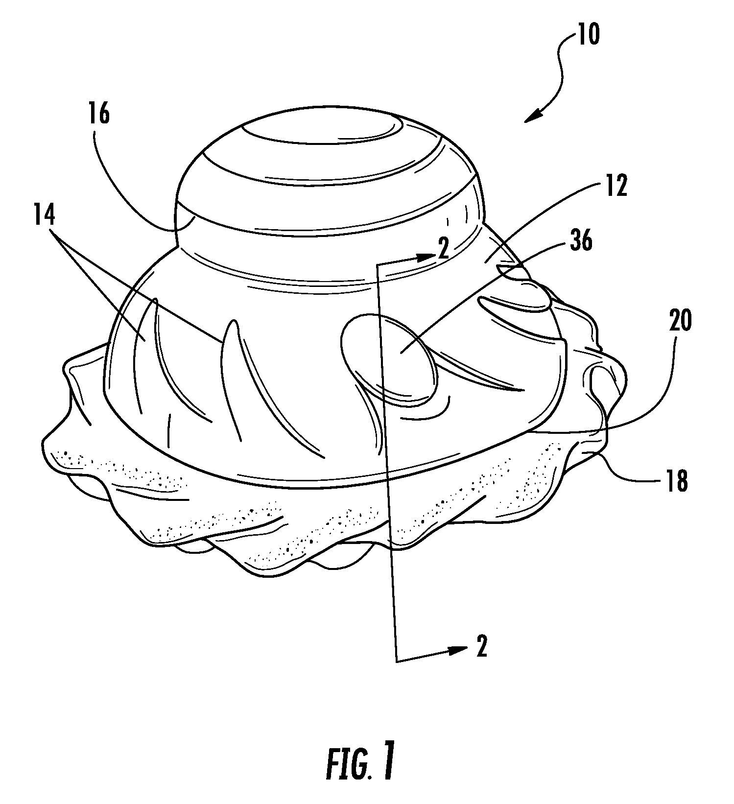
[0021]Now referring to the drawings, the dispensing device of the present invention is shown and generally illustrated at 10 in FIG. 1. As was stated above, the present invention is generally directed to a novel and unique surface scrubber device that includes an integrated fluid dispenser positioned therein. In this regard, fluid dispenser serves to dispense a fluid into the scrubbing pad of the device to improve the cleaning effectiveness of the device.

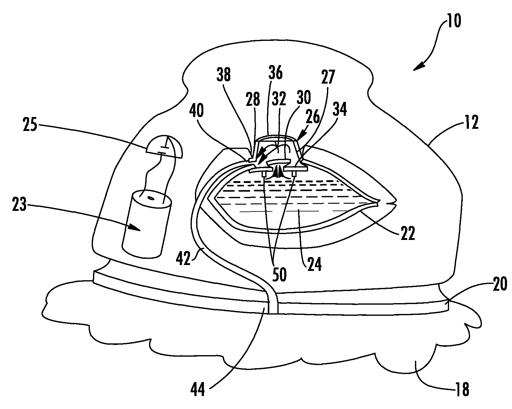
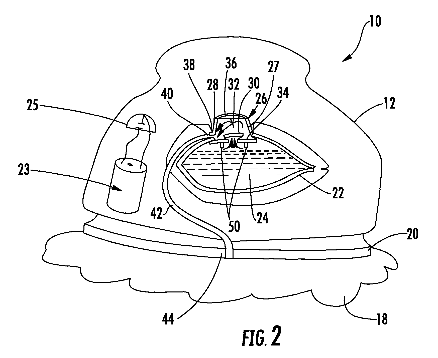
[0022]Generally, the dispensing device 10 of the present invention includes a main body 12 that is preferably made of a rigid, semi-rigid or soft base material and is configured to be suitable for grasping by a user's hand. In this manner, surface enhancements 14 or gripping contours 16 may be provided to enhance the user's ability to grasp and retain the device 10. A pad member 18 can be seen attached to an engagement surface 20 positioned on one side of the main body 12. Further, as will be described below in connection with FIG. ...


PUM


Abstract

A cleaning device includes an integral fluid dispenser therein that serves to dispense a fluid into the scrubbing pad of the device to improve the cleaning effectiveness of the device. The device includes a main body with a cleaning pad attached to one side thereof, an internal motorized assembly for rotating the cleaning pad upon depressing a button provided on a side of the main body and a fluid storage region that contains a cleaning fluid. A metered dosing pump is used to dispense a measured amount of fluid from the fluid storage region to cleaning pad upon actuation by the user. Further, the dispensing action and the rotation of the pad may be controlled by the same button or by separate buttons.

Description

CROSS-REFERENCE TO RELATED APPLICATIONS[0001]This application is related to and claims priority from earlier filed U.S. Provisional Patent Application No. 60 / 891,338 filed Feb. 23, 2007.BACKGROUND OF THE INVENTION[0002]The present invention relates generally to product packaging and / or containers that include integrated dispensing devices. More specifically, the present invention relates to device that allows the user to introduce a metered dose of fluid in a controlled fashion into or onto the surface of a cleaning pad applicator prior to or during use.[0003]Various types of fluid material and media are employed for different purposes throughout commerce and industry. For example, there are various products in the areas of personal care, home care, air care, transportation care and food industries that require a fluid material to be dispensed in some manner from a source of such material. Further, when this material is sold in commerce, it must be contained and stored in some type ...

Claims


Application Information

Patent Timeline
Patent Type & Authority Patents(United States)
IPC IPC(8): A46B11/02
CPCA45D34/04A47K7/03A47L13/26G01F11/08A45D2200/1018A45D2200/1054
Inventor LAFLAMME, ROGER J.WARNER, JIM F.
Owner 1TOUCH HLDG INC
Why Eureka
Try Eureka