

Injection device
- Summary
- Abstract
- Description
- Claims
- Application Information
AI Technical Summary
Benefits of technology
Problems solved by technology
Method used
Image

Examples
first embodiment
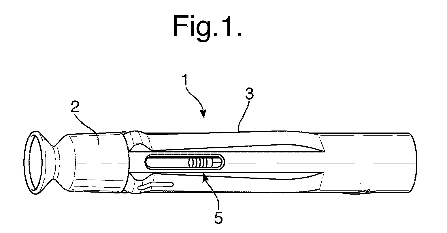
[0247]the invention will be described with respect to FIGS. 1 to 29. FIG. 1 shows an automatic injection device in accordance with one embodiment of the invention. FIG. 1 shows the device after removal from any blister pack secondary packaging, and prior to use to administer an injection.
[0248]The device 1 has a rear end towards the right-hand side of the device in FIG. 1, and a front end towards the left-hand side of the device in FIG. 1. The device 1 includes an end cap 2 and a rear outer housing 3. The front end is the needle end of the device. In use, the end cap 2 is removed by a user to expose the front, needle end of the device. The rear outer housing 3 is gripped by the user during operation of the device to hold the front end against the skin. The rear housing 3 is provided with a tactile surface covering, and may includes ribs and other surface formations to facilitate gripping of the device, particularly if the device is intended for use with those with impaired manual de...
PUM
 Abstract
Description
Claims
Application Information