Optimized placement policy for solid state storage devices

a technology of solid-state storage and placement policy, which is applied in the field of computer data storage systems, can solve the problems of slow access time, reliability problems, and mechanical hard drives suffering in certain areas

Inactive Publication Date: 2007-12-13
BITMICRO LLC
View PDF4 Cites 170 Cited by
  • Summary
  • Abstract
  • Description
  • Claims
  • Application Information

AI Technical Summary

Benefits of technology

[0009]In one embodiment of the invention, a remap table is used to map all logical addresses from a host system to the actual physical addresses where data are stored. The assignments of these physical locations are done in such a way that the load of the system is evenly distributed to its available resources. This would ensure that the storage system will run at its utmost efficiency utilizing its resources properly. To achieve this, the system would make sure that the physical location of data be evenly distributed according to the current load of the system.

Problems solved by technology

Mechanical hard drives suffer in areas unseen in flash memory based drives due to its many moving parts (electrical motor, spindle shaft, read / write head, and a magnetic rotating disk).
This leads to reliability problems especially when exposed to vibration and shock.
Not only that, it also causes slow access time when fetching data from different areas of mechanical drive.
Since flash memory based drives typically have no moving parts, it can easily withstand harsh environmental conditions and physical mishandling that would lead to failures in regular mechanical drives.
However, there are also several problems associated with using flash based drives over rotating drives.
Flash devices cannot be written to when it is not in the erased state.
Typical flash technology (specifically NAND flash) doesn't allow toggling of individual bytes from a programmed state back to its erased state.
Considering that erase operations typically takes much longer in comparison to write or read operations, this greatly impacts the performance of the system.
Another unique characteristic of flash memory devices is that it has the tendency to wear-out when subjected to a certain amount of erase cycles (typically 100K).
This wearing-out leads to bad blocks and thus requires some sort of a bad block management to handle this.

Method used


Image

  • Optimized placement policy for solid state storage devices
  • Optimized placement policy for solid state storage devices
  • Optimized placement policy for solid state storage devices

Examples


Embodiment Construction

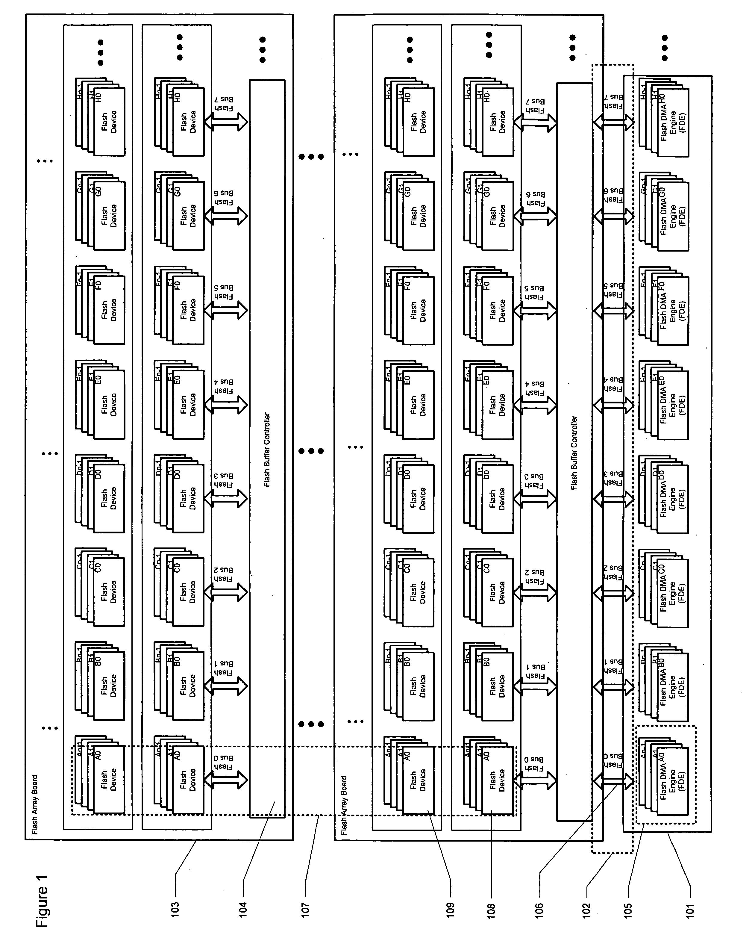
[0025]FIG. 1 shows an exemplary architecture that accommodates a very large number of flash arrays to achieve large capacities according to an embodiment of the present invention. The system comprises a number of Flash DMA Engines (FDEs) 101. A Flash DMA Engine (FDE) is basically an intelligent DMA controller that facilitates high speed data transfers to / from a group of flash memory devices. The system also contains a set of Flash Buses 102, which is a bus interface used by the FDE to connect to the flash memory devices. To increase capacity, a number of expansion boards 103 can be added. An expansion board is essentially a memory board that consists of a pool of flash memory devices for additional storage and a Flash Buffer Controller 104 for communication to the Flash DMA Engine. The Flash Buffer Controller is a controller that drives the Flash Bus and translates the command signals from the FDEs into native flash commands that can be understood by the target flash chip. The numbe...


PUM


Abstract

A data storage system is provided comprising several flash arrays in a board and stacking these boards to attain a high-capacity solid state hard drive. A remap table is used to map all logical addresses from a host system to the actual physical addresses where data are stored. The assignments of these physical locations are done in such a way that the load of the system is evenly distributed to its available resources. This would ensure that the storage system will run at its utmost efficiency utilizing its resources properly. To achieve this, the system would make sure that the physical location of data be evenly distributed according to the current load of the system.

Description

BACKGROUND[0001]1. Field[0002]The present invention relates to computer data storage systems. More particularly, the present invention relates to a system and method of mapping all logical addresses from a host system to physical addresses of data storage devices for improving host computer data access performance.[0003]2. Description of Related Art[0004]As flash devices are getting cheaper, solid state based hard drives are getting more popular as replacement for traditional mechanical hard drives. Mechanical hard drives suffer in areas unseen in flash memory based drives due to its many moving parts (electrical motor, spindle shaft, read / write head, and a magnetic rotating disk). This leads to reliability problems especially when exposed to vibration and shock. Not only that, it also causes slow access time when fetching data from different areas of mechanical drive.[0005]Since flash memory based drives typically have no moving parts, it can easily withstand harsh environmental co...

Claims


Application Information

Patent Timeline
Patent Type & Authority Applications(United States)
IPC IPC(8): G06F12/00
CPCG06F12/0246G06F2212/1016G06F2212/1036G06F2212/7201G06F2212/7208G06F2212/7211
Inventor ARCEDERA, MARKLANUZA, REYJANBABAYLAN, RITCHIE
Owner BITMICRO LLC
Why Eureka
Try Eureka