Circularly-polarized-wave patch antenna which can be used in a wide frequency band

a patch antenna and circularly polarized wave technology, applied in the direction of waveguide devices, resonance antennas, coupling devices, etc., can solve the problems of difficult to ensure the isolation of a pair of transmission lines connected to the 90°-phase-difference circuit of the patch electrode, and difficulty in providing electric power

Inactive Publication Date: 2005-10-04
ALPS ALPINE CO LTD
View PDF10 Cites 180 Cited by
  • Summary
  • Abstract
  • Description
  • Claims
  • Application Information

AI Technical Summary

Benefits of technology

[0013]In the patch antenna having such a feeder circuit, the 90°-phase-difference circuit and the Wilkinson distribution circuit are provided on a lower surface of a circuit board, which is fixed to a lower surface of the ground electrode of the main body in a laminating manner, upper ends of two feeding pins which extend through the dielectric substrate and the circuit board are connected to the feeding points, and lower ends of the two feeding pins are connected to the output terminals of the 90°-phase-difference circuit. With this configuration, the main body and the circuit board are integrated, so that a compact patch antenna which can be used in a wide band can be preferably obtained. In this case, the dielectric substrate of the main body and the circuit board used for the feeder circuit may be included in a multilayer substrate. Also, instead of using the two feeding pins, two microstrip lines may be connected to the patch electrode for performing feeding. In this configuration, by providing the 90°-phase-difference circuit and the Wilkinson distribution circuit between the microstrip lines and the feeder line, the patch antenna can be used in a wider band.

Problems solved by technology

However, in a known patch antenna of a two-point feeding type, it is not easy to supply electric power to the two feeding points of the patch electrode over a wide frequency band without reflection.
Further, since reflection of signal waves is more likely to increase due to the limited frequency band of the patch antenna itself, a favorable reflection characteristic cannot be obtained in a wide band.
This is because isolation of a pair of transmission lines of the 90°-phase-difference circuit connected to the patch electrode is difficult to ensure.

Method used


Image

  • Circularly-polarized-wave patch antenna which can be used in a wide frequency band
  • Circularly-polarized-wave patch antenna which can be used in a wide frequency band
  • Circularly-polarized-wave patch antenna which can be used in a wide frequency band

Examples


Embodiment Construction

[0018]Hereinafter, an embodiment of the present invention will be described with reference to the above listed figures.

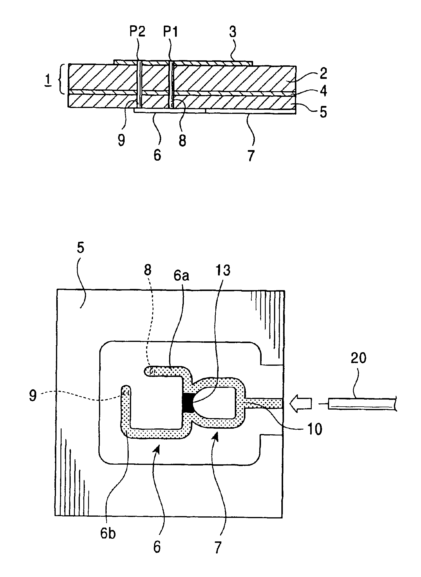
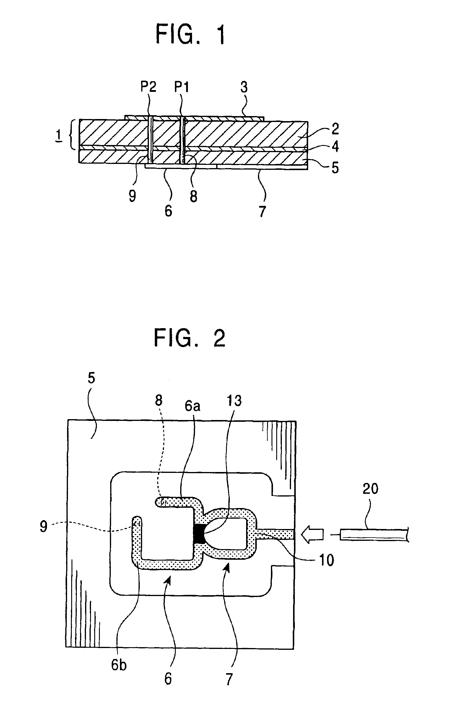
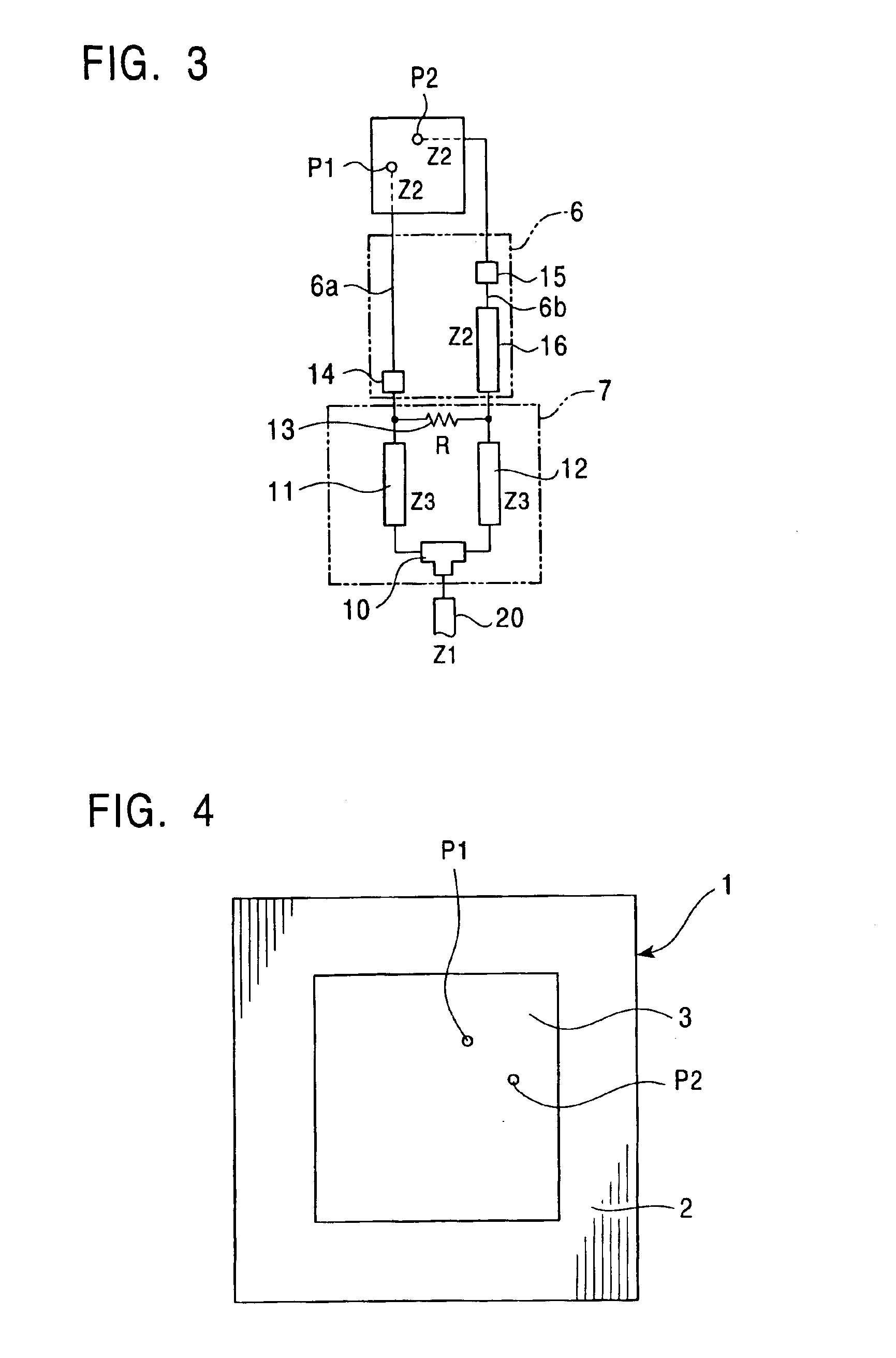
[0019]The patch antenna shown in the above listed FIGS. 1, 2, 3, and 4, includes a main body 1 having a dielectric substrate 2; a patch electrode 3 provided on an upper surface of the dielectric substrate 2; and a ground electrode 4 formed on an entire lower surface of the dielectric substrate 2. Further, a circuit board 5 is fixed to a lower surface of the ground electrode 4 of the main body 1 in a laminating manner. Also, a 90°-phase-difference circuit 6 and a Wilkinson distribution circuit 7 are provided on a lower surface of the circuit board 5.

[0020]Two feeding points P1 and P2 are provided in the patch electrode 3 of the main body 1. These feeding points P1 and P2 are defined by the upper ends of two feeding pins 8 and 9, the upper ends being soldered to predetermined positions of the patch electrode 3. As shown in FIG. 1, the feeding pins 8 and 9 extend throu...


PUM


Abstract

A circularly-polarized-wave patch antenna includes a main body having a patch electrode provided with two feeding points and a circuit for generating a phase difference of 90° between signals supplied to the feeding points. A Wilkinson distribution circuit is provided between the 90°-phase-difference generating circuit and a coaxial cable (feeder line) so as to improve a reflection characteristic. The patch antenna includes two feeding points, and thus a favorable axial ratio characteristic can be obtained in a wide band. Also, a favorable reflection characteristic can be obtained in a wide band because of the Wilkinson distribution circuit. Accordingly, the patch antenna can be used in a wider frequency band.

Description

BACKGROUND OF THE INVENTION[0001]1. Field of the Invention[0002]The present invention relates to a circularly-polarized-wave patch antenna. In particular, the present invention relates to a configuration of a feeder circuit thereof.[0003]2. Description of the Related Art[0004]In recent years, patch antennas, which are compact and thin circularly-polarized-wave antenna, have been becoming widespread. In this type of patch antenna, a main body of the antenna is formed by providing a patch electrode and a ground electrode on both principal surfaces of a dielectric substrate. In this configuration, a predetermined high-frequency signal is supplied to a feeding point of the patch electrode so as to excite two orthogonal modes whose phases are different by 90°. Accordingly, a circularly polarized radio wave is radiated.[0005]A single-point feeding method or a two-point feeding method can be adopted in a circularly-polarized-wave patch antenna. In general, a single-point feeding method is ...

Claims


Application Information

Patent Timeline
Patent Type & Authority Patents(United States)
IPC IPC(8): H01Q9/04H01Q13/08H01P5/19
CPCH01Q9/0435
Inventor YUANZHU, DOU
Owner ALPS ALPINE CO LTD
Why Eureka
Try Eureka