Surface acoustic wave resonator, surface acoustic wave device, and communications equipment

a surface acoustic wave and resonator technology, applied in the direction of impedence networks, electrical apparatus, etc., can solve the problems of increasing the insertion loss of surface acoustic wave filters, unable to adjust the resonance mode generated in the pass band, and difficulty in sufficiently obtaining the antenna gain, etc., to achieve the effect of reducing the insertion loss, increasing the degree of design freedom of the pass band, and increasing the degree of out-of-band attenu

Active Publication Date: 2007-02-01
KYOCERA CORP
View PDF2 Cites 16 Cited by
  • Summary
  • Abstract
  • Description
  • Claims
  • Application Information

AI Technical Summary

Benefits of technology

[0026] In the above-mentioned configuration, if a surface acoustic wave resonator comprising an IDT electrode and reflector electrodes with the IDT electrode sandwiched therebetween for generating one or more mode resonances is connected in series or in parallel with the IDT electrodes composing the surface acoustic wave resonator, impedance matching can be achieved. Thus, it is possible to form an attenuation pole by connecting the surface acoustic wave resonator. Therefore, characteristics can be controlled so as to satisfy specifications required for an out-of-band attenuation to be increased while widen...

Problems solved by technology

The reason for this is that in the mobile communications equipment, the transition of antennas for miniaturization from conventional whip antennas to built-in antennas using dielectric ceramics has occurred, which makes it difficult to sufficiently obtain the gains of the antennas, so that requests to further improve the insertion losses of the surface acoustic wave filters have increased.
However...

Method used


Image

  • Surface acoustic wave resonator, surface acoustic wave device, and communications equipment
  • Surface acoustic wave resonator, surface acoustic wave device, and communications equipment
  • Surface acoustic wave resonator, surface acoustic wave device, and communications equipment

Examples


example 1

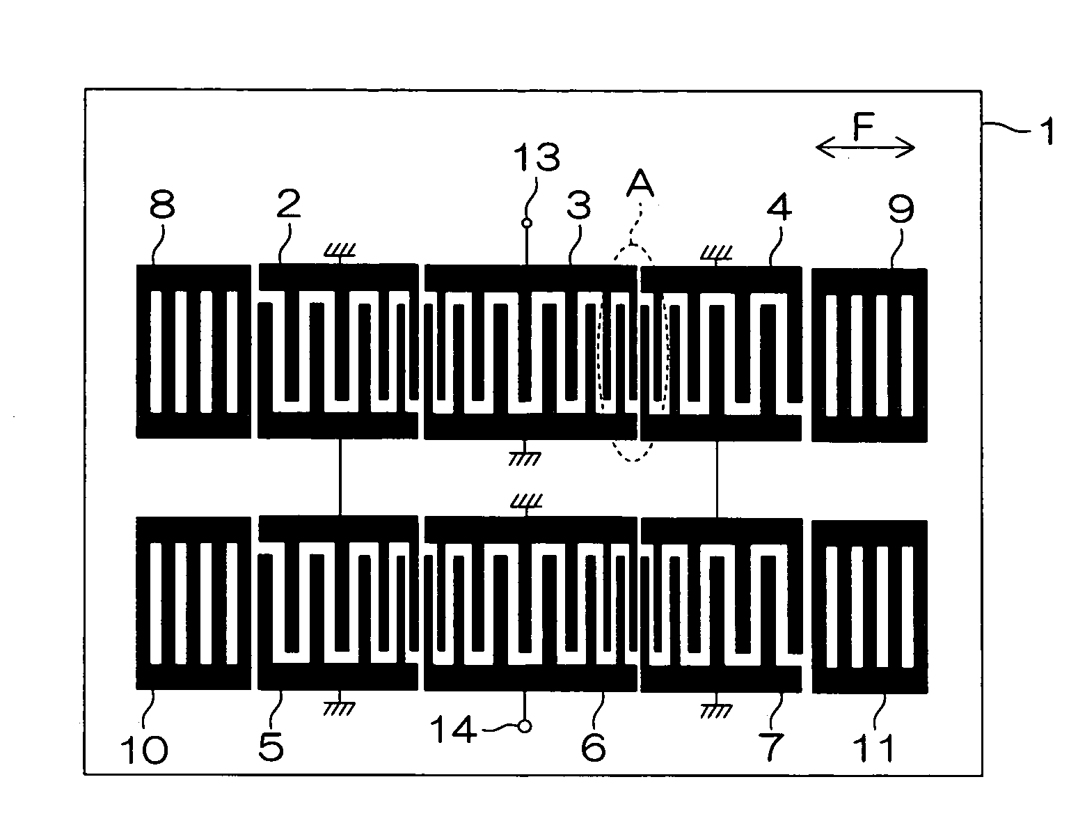
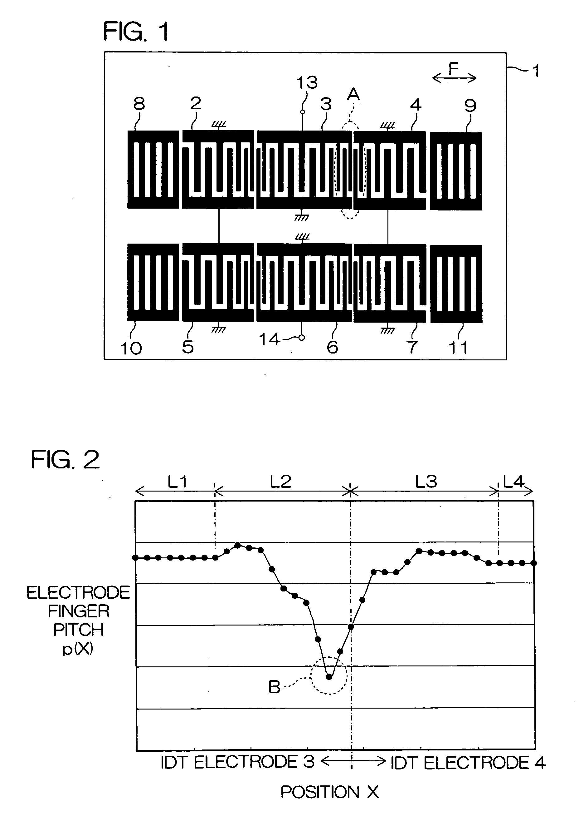
[0108] An example in which the surface acoustic wave apparatus shown in FIG. 1 is specifically manufactured will be described.

[0109] In the surface acoustic wave apparatus, each of two adjacent IDT electrodes 3 and 4 comprises variable pitch sections L2 and L3, which are sections in close proximity to an end of the other IDT electrode, where the electrode finger pitch is variable and fixed pitch sections L1 and L4, which are the remaining sections, where the electrode finger pitch is fixed and is different from that in the variable pitch sections. The electrode finger pitch in the variable pitch sections L2 and L3 decreases toward the boundary between the variable pitch sections, and the minimum electrode finger pitch portion B is on one side spaced apart from the boundary.

[0110] A fine electrode pattern composed of an Al (99 mass %)—Cu (1 mass %) alloy was formed on a piezoelectric substrate 1 composed of a 38.7° Y-cut X-propagation LiTaO3 single crystal.

[0111] The electrode fin...

example 2

[0128] A surface acoustic wave apparatus similar to that in the example 1 was manufactured.

[0129] The example 2 differs from the example 1 in that in a surface acoustic wave resonator in the surface acoustic wave apparatus in the example 2, an electrode finger pitch in adjacent IDT electrodes 3 and 4 in the vicinity of the boundary between the IDT electrode 3 and 4 have a profile as shown in FIG. 5. That is, the minimal electrode finger pitch portion C in two variable pitch sections L2 and L3 as shown in FIG. 5 has three minimal positions.

[0130] The average electrode finger pitch in the variable pitch section L2 on the side of the IDT electrode 3 was 2.01 μm, and the electrode finger pitch in the fixed pitch section L1 was set to 2.12 μm.

[0131] The average electrode finger pitch in the variable pitch section L3 on the side of the IDT electrode 4 was 2.05 μm, and the electrode finger pitch in the fixed pitch section L4 was set to 2.10 μm.

[0132] The minimum portion B in the minima...

example 3

[0136] A surface acoustic wave apparatus similar to that in the example 1 was then manufactured.

[0137] The example 3 differs from the example 1 in that the electrode finger pitch in adjacent IDT electrodes 3 and 4 in the vicinity of the boundary between the IDT electrode 3 and 4 in a surface acoustic wave resonator has a profile as shown in FIG. 7.

[0138] That is, the surface acoustic wave resonator has a wide pitch region D in a variable pitch section L3 on the side of the IDT electrode 4. Further, the maximum electrode finger pitch portion B in the two variable pitch sections L2 and L3 is positioned offset by 4.05 μm toward the IDT electrode 3 on one side spaced apart from the boundary between the two adjacent IDT electrodes 3 and 4.

[0139] A graph of frequency characteristics in the vicinity of a pass band in the surface acoustic wave apparatus is shown in FIG. 11. FIG. 11 is a graph showing frequency dependency of an insertion loss representing filter transmission characteristi...


PUM


Abstract

A plurality of IDT electrodes 2 to 7 each having a large number of electrode fingers extending in a direction perpendicular to a propagation direction of a surface acoustic wave propagating on a piezoelectric substrate 1 are arranged on the piezoelectric substrate 1 along the propagation direction, and each of the two adjacent IDT electrodes out of the plurality of IDT electrodes 2 to 7 comprises a variable pitch section and a fixed pitch section. The electrode finger pitch in the variable pitch section gradually decreases toward the boundary between the two adjacent IDT electrodes, and the minimum electrode finger pitch portion in the two variable pitch sections is on one side spaced apart from the boundary. There can be provided a surface acoustic wave apparatus having a large pass bandwidth, having a low insertion loss, and having improved flatness in a pass band.

Description

BACKGROUND OF THE INVENTION [0001] 1. Field of the Invention [0002] The present invention relates to a surface acoustic wave apparatus used for a surface acoustic wave filter or the like, and communications equipment comprising the same. [0003] 2. Description of Related Art [0004] Conventionally, as frequency selecting filters used for RF stages in mobile communications equipment such as cellular phones and automobile telephones, surface acoustic wave filters have been widely used. Generally, as characteristics required of the frequency selecting filters, various characteristics such as wide pass bands, low losses, and high attenuations are listed. [0005] In recent years, particularly in order to improve receiving sensitivity and reduce power consumption in the mobile communications equipment, requests to reduce the losses of the surface acoustic wave filters have increased. The reason for this is that in the mobile communications equipment, the transition of antennas for miniaturiz...

Claims


Application Information

Patent Timeline
IPC IPC(8): H03H9/64
CPCH03H9/14576H03H9/6469H03H9/14588H03H9/14582
Inventor OTSUKA, KAZUHIROMAKIBUCHI, DAISUKENAKAI, TSUYOSHIFUKUURA, ATSUOMITANAKA, HIROYUKIOBARA, IKUOIIOKA, KIYOHIRO
Owner KYOCERA CORP
Why Eureka
Try Eureka