Cascading optical multiplexing device

a multiplexing device and optical technology, applied in multiplex communication, optical elements, instruments, etc., can solve the problems of poor efficiency and stability, poor efficiency, and poor stability of the alignment system, and achieve high efficiency and compact multiplexing and demultiplexing, reduce polarization dependent effects, and reduce loss

Inactive Publication Date: 2000-12-26
CORNING OCA CORPORATION
View PDF5 Cites 50 Cited by
  • Summary
  • Abstract
  • Description
  • Claims
  • Application Information

AI Technical Summary

Benefits of technology

It is a significant advantage of at least certain preferred embodiments, that significant reduction in assembly cost and complexity can be achieved. Most notably, the "kitting" of filters is less costly and complex. Since each of the multiple WDMs in a cascade has a smaller number of channel ports than would be required in one larger WDM, filter elements need be collected together in smaller kits. That is, fewer filters must be kitted together for each of the smaller WDMs used in a cascaded WDM arrangement in accordance with this disclosure. Consequently, the filters of a given kit can be more precisely matched to each other. That is, within cost, time and complexity constraints of a typical WDM assembly operation, filters can be better matched as to their deviation from center wavelength. The assembled WDM can, therefore, be more precisely tuned for all of its channel ports.
It is on additional surprising result of this invention that significantly reduced insertion loss can be achieved by optical multiplexing devices for 8, 16 or more channels using cascaded WDMs in accordance with this disclosure. As mentioned above, insertion loss increases with distance traveled by an expanded beam. In fact, insertion loss increases rapidly beyond the distance traveled by an expanded beam in a current four-port WDM. Whereas insertion loss may be only, e.g., 1 dB over the distance traveled in a typical expanded beam four-port WDM, insertion loss would typically increase to more than double if the zigzag expanded beam light path were extended within such WDM to eight channels (using comparable quality componentry). The deterioration significantly increases, if such WDM were enlarged to 16 channels. In typical preferred embodiments, the insertion loss associated with each cascade, that is, associated with passing multiple channels from one WDM to the next WDM may be only about 1 / 2 dB to 1 dB. Thus, by the use of cascading WDMs in accordance with this disclosure an overall reduction in insertion loss can be achieved.
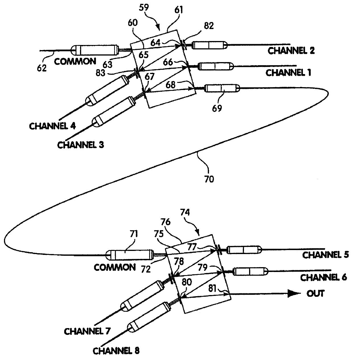
In accordance with another aspect, one or more of the cascaded WDMs employed in the optical multiplexing devices disclosed here employs channel interleaving. More specifically, in a multiplexer defining at least three optical ports in sequence from the common port, a first channel port is substantially transparent to a first wavelength sub-range and substantially reflective of other wavelengths. A second channel port sequentially following the first channel port is substantially transparent to a second wavelength sub-range and substantially reflective of other wavelengths. A third port sequentially following the second channel port is substantially transparent to a third wavelength sub-range which is intermediate the first and second wavelength sub-ranges. More specifically, the third wavelength sub-range is intermediate in that the numerical value of its center wavelength is numerically greater than one and less than the other of the first and second sub-ranges. Thus, individual channels or wavelength sub-ranges are removed from a multi-channel light beam in a nonsequential order. In accordance with certain especially preferred embodiments, an interleaving mode is employed which can be referred to as compounded interleaving of the optical ports, wherein one or more channels added and / or removed by a first WDM are interleaved with other channels which are added and / or removed by a second WDM cascaded with the first WDM. Here, again, the channels are interleaved in that the respective wavelength sub-range(s) of the one or more channels of the first WDM are intermediate (by wavelength size) the sub-ranges of the channels of the second WDM. It should be understood that an interleaved channel in such compounded interleaving may actually be a multi-channel wavelength sub-range, and it may be positioned sequentially at one end of the sequence of channels handled by the optical multiplexing device. As will be apparent from the discussion below of various preferred embodiments, significant advantages can be realized through implementation of channel interleaving, especially in the context of cascaded WDMs. Notably, for example, the cost, assembly and design complexity, and insertion loss associated with post filters can be reduced. Post filters may be unnecessary at a channel port if the one or two adjacent wavelength sub-ranges have previously been removed from the multi-channel light beam. Moreover, in certain preferred embodiments in low loss and more uniform variation in signal strength can be achieved by matching the insertion loss contributed by a post filter for one channel port with the insertion loss associated with cascading other channels to a next WDM through a different channel port at which no post filter is required due to channel interleaving.
Those skilled in the art, that is those with knowledge or experience in this technology, will recognize that a certain unavoidable overlap, or cross talk, occurs from each channel to the other channels. As noted above, this occurs because of the inability of a WDM to separate one channel perfectly from the multiplexed signal. In a WDM using Fabry-Perot type interference filters, better signal isolation can be achieved using a filter having a higher figure of merit. A filter with a greater number of cavities typically will have a higher FOM than an otherwise comparable filter with fewer cavities, but also is more expensive to produce and causes increased insertion loss. Post filters also can improve signal isolation, but also add cost and increase insertion loss. Signal contamination is naturally greater from channels that are adjacent to one another. Thus, although a third channel will have some overlap with the first channel, it is typically much less than that occurring with the adjacent second and fourth channels. As now described with reference to certain preferred embodiments, improved signal isolation with reduced insertion loss can be achieved using cascaded WDMs, especially in connection with interleaving. Of course, better quality filters and / or post filters, etc., can be used in conjunction with the cascading and interleaving features disclosed here, to achieve corresponding further improvements in system performance.
It is to be appreciated that the number of channel ports in any of the present optical multiplexing devices can vary, for example, from two, to four, to eight, and even more. By constructing such an optical multiplexing device with four-port WDMs, however, a significant advantage can be realized. 
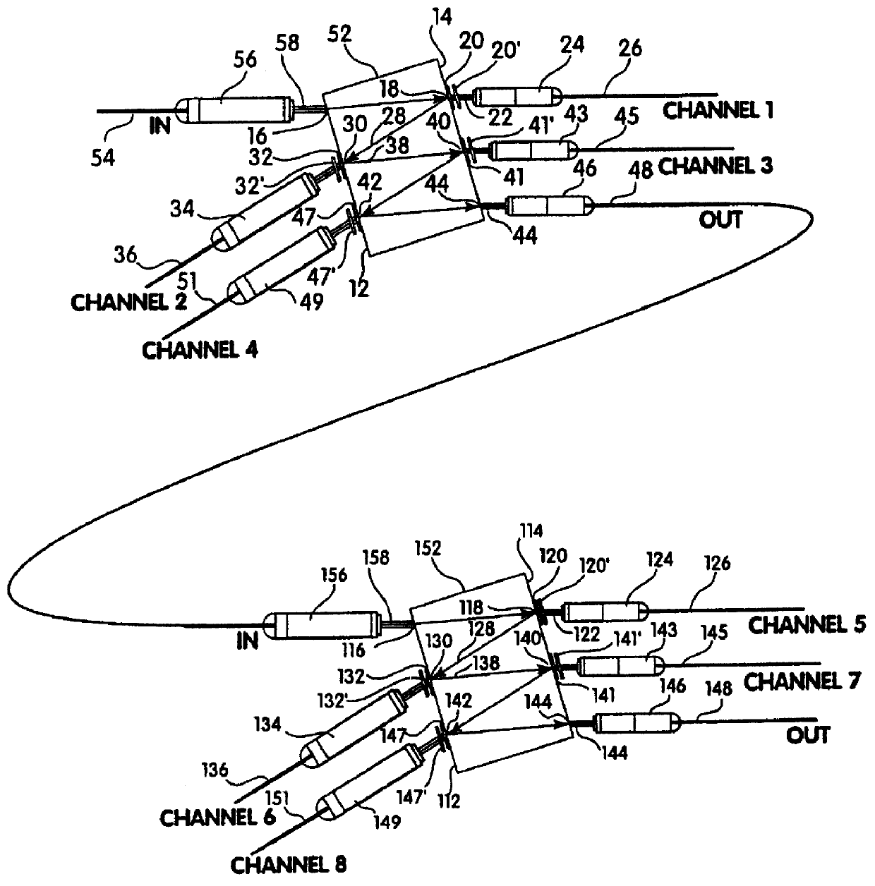
Light beam divergence increases as the light beam travels along the multi-point light path within the optical multiplexing device. Placing a collimator at the residual port 44 of the first of the cascaded WDMs collimates the light again, and cascading two such four-port WDMs results in less loss due to such beam divergence than would a comparable single 8-port WDM. It is a significant advantage realized by the optical multiplexing devices with cascaded WDMs disclosed here, that the signal degradation, i.e., insertion loss, etc., caused by a cascade connection of one WDM to another, typically only about 1 / 2 dB to 1 dB using optical components currently commercially available, is less than the signal degradation which would occur in an expanded beam WDM enlarged to 8 or 16 channel ports. The advantage is even greater when a cascade of three or four WDMs is compared to a comparable single WDM enlarged to 16 channel ports.
It will be recognized by those skilled in the art that the optical multiplexing device illustrated in FIG. 1 can provide highly efficient and compact multiplexing and demultiplexing functionality. The optical block can have a width, e.g., of about 14.5 mm and a height of about 5.5 mm. Linear spacing of the optical ports on each of surfaces 12 and 14 can be, for example, about 3.0 mm, with an overall linear dimension of approximately 21.6 mm for the optical block. Generally, it is preferred in devices of the type discussed here, to have a low entry angle or tilt angle (where zero degrees would be normal to the surface of the optical block) at which light passes through the common port 16 (measuring the angle of the light outside the optical block) to reduce polarization dependent effects. It also reduces adverse effects of collimated light divergence on filter performance, since a lower entry angle results in more closely spaced bounce points within the optical block and, therefore, a shorter travel path for the light. Typically, the entry angle is less than 30, being preferably from 4 to 15, more preferably 6 to 10, most preferably about 8.

Problems solved by technology

The cost of new installed fiber-optic cable presents a barrier to increased carrying capacity, which can be addressed by wavelength division multiplexing.
Gratings and prisms typically require complicated and bulky alignment systems and have been found to provide poor efficiency and poor stability under changing ambient conditions.
Achieving the objective of multiplexing signals ever more densely presents certain problems.
There are practical limits on the distance a multi-channel light beam can travel as an expanded beam before unacceptable signal degradation occurs.
Four-channel multiplexing, however, does not meet the growing need for 8 channel multiplexing systems, 16 channel systems, etc.
It has not proved acceptable for many applications to simply enlarge current WDM devices to extend the zigzag expanded beam to impinge in sequence on 8 or 16 interference filters.
The longer distance traveled by the expanded beam is found to cause undesirable signal degradation.
A related problem in developing WDMs of the type discussed above employing multiple filter elements mounted in parallel to an optical block, for multiplexing more than four channels, especially expanded beam WDMs using selectively transparent filter elements, lies in the difficulty of "kitting" the larger number of filter elements.
Kitting the filters is an assembling task, however, which becomes more complex, more expensive and more time consuming as the number of filters in the kit increases.
Thus enlarging a 4-port WDM to an 8-port WDM would involve an undesirable increase in assembly time, cost and complexity to collect the kits of eight filters.
The problem would be far worse for a 16 channel WDM.
Another problem hindering the development of wavelength division multiplexing systems with greater numbers of channels involves channel spacing.
The passband of even a high quality interference filter is imperfect, however, such that not only the desired wavelength sub-range assigned to a particular channel is passed, but also to a lesser extent adjacent wavelengths (i.e., adjacent channels) are unavoidably passed by the filter along with the desired signal for that channel.
Filters having a better FOM are more costly to produce and, hence, are unsuitable for many applications.
Thus, the intermediate wavelengths are simply not used, resulting in the need to use instead less desirable wavelengths at the outside of the long and short bands.
As mentioned above, insertion loss increases with distance traveled by an expanded beam.
In fact, insertion loss increases rapidly beyond the distance traveled by an expanded beam in a current four-port WDM.

Method used


Image

  • Cascading optical multiplexing device
  • Cascading optical multiplexing device
  • Cascading optical multiplexing device

Examples


Embodiment Construction

The optical multiplexing device, as disclosed above, has numerous applications including, for example, in fiber-optic telecommunication systems. Optical multiplexing devices of this design also have application, for example, in test equipment and the like, as well as laboratory instrumentation. For purposes of illustration, the preferred embodiments described below in detail are dense channel wavelength division multiplexing devices for multi-channel fiber-optic telecommunication systems employing 8 channels, 16 channels or more. The above-described problems of signal degradation and losses due to light beam divergence, cross talk losses, etc. from adjacent channels are reduced in such fiber-optic telecommunication systems.

Transparent, when used here, means at least substantially transparent to a particular wavelength range or wavelength sub-range. Reflective, when used here, means at least substantially reflective of particular wavelength ranges or wavelength sub-ranges. Residual l...


PUM


Abstract

An optical multiplexing device is provided comprising multiple wavelength division multiplexers cascaded together. A first one of the wavelength division multiplexers has a common port and multiple optical ports which are optically coupled to the common port. The common port may be optically coupled to a trunk line of a system employing wavelength division multiplexing, for example, a fiber-optic telecommunication system employing 4, 8, 16 or other number of multiplexed channels. The optical ports include multiple channel ports, each of which is transparent to a corresponding wavelength sub-range and reflective of other wavelengths. The second wavelength division multiplexer has a common port optically coupled to one of the optical ports of the first wavelength division multiplexer. The second wavelength division multiplexer also has multiple optical ports which are optically coupled to its common port and include multiple wavelength-selective channel ports. A waveguide, such as a fiber-optic line, can optically connect the common port of the second wavelength division multiplexer to an optical port of the first wavelength division multiplexer. The cascaded WDMs each may be optically coupled to the output of a passive coupler and a housing may be provided defining an enclosed space in which the optical multiplexing device is mounted. Optionally, additional WDMs may be cascaded with the first two WDMs in a parallel or branched formation, an in-line formation or some combination. Preferably, the channels are interleaved, such that they are removed from the multiplexed signal in certain non-sequential order. The optical multiplexing device also may employ compound interleaving wherein adjacent channels are multiplexed by different ones of the cascaded WDMs. The optical multiplexing devices can operate to add signals, remove signals or a combination of both.

Description

1. Field of the InventionThe present invention is directed to an optical multiplexing device which spatially disburses multi-channel collimated light from an optical waveguide into individual channels, each of which can be directed to an individual optical waveguide, light detector, etc., and / or multiplexes channels to a common optical waveguide or other destination. In certain preferred embodiments, the optical multiplexing devices of the present invention are particularly well suited for dense channel wavelength division multiplexing systems for fiber-optic telecommunications systems.2. Technical BackgroundWavelength division multiplexing of optical signals is finding widespread use in various fields, especially including data transmission and other telecommunication applications. The cost of new installed fiber-optic cable presents a barrier to increased carrying capacity, which can be addressed by wavelength division multiplexing. Wavelength division multiplexing allows multiple...

Claims


Application Information

Patent Timeline
Patent Type & Authority Patents(United States)
IPC IPC(8): G02B6/34H04J14/02G02B6/293H04J14/00
CPCG02B6/2938G02B6/29367H04J14/02G02B6/29386G02B6/12007G02B6/2932H04J14/0213G02B2006/12109
Inventor GRASIS, MICHAEL E.SCOBEY, MICHAEL A.SPOCK, DEREK E.
Owner CORNING OCA CORPORATION
Why Eureka
Try Eureka