Piezoelectric thin-film filter

a thin-film filter and piezoelectric technology, applied in the direction of impedence networks, electrical devices, etc., can solve the problems of deteriorating steepness of the shoulder characteristic of the filter, increasing insertion loss, etc., and reducing the ripple in the passband. , the effect of reducing the insertion loss

Active Publication Date: 2010-01-21
MURATA MFG CO LTD
View PDF13 Cites 48 Cited by
  • Summary
  • Abstract
  • Description
  • Claims
  • Application Information

AI Technical Summary

Benefits of technology

[0011]Accordingly, preferred embodiments of the present invention provide a piezoelectric thin-film filter that reduces the insertion loss and deterioration of the steepness of the shoulder characteristic and reduces ripples in the passband.

Problems solved by technology

The second resonator including the second vibration portion having an irregular or asymmetrical plan view shape, has increased insertion loss and deteriorated steepness of the shoulder characteristic of the filter.

Method used


Image

  • Piezoelectric thin-film filter
  • Piezoelectric thin-film filter
  • Piezoelectric thin-film filter

Examples


first preferred embodiment

[0061]A piezoelectric thin-film filter 10 according to the first preferred embodiment will be described with reference to FIGS. 1 to 6B.

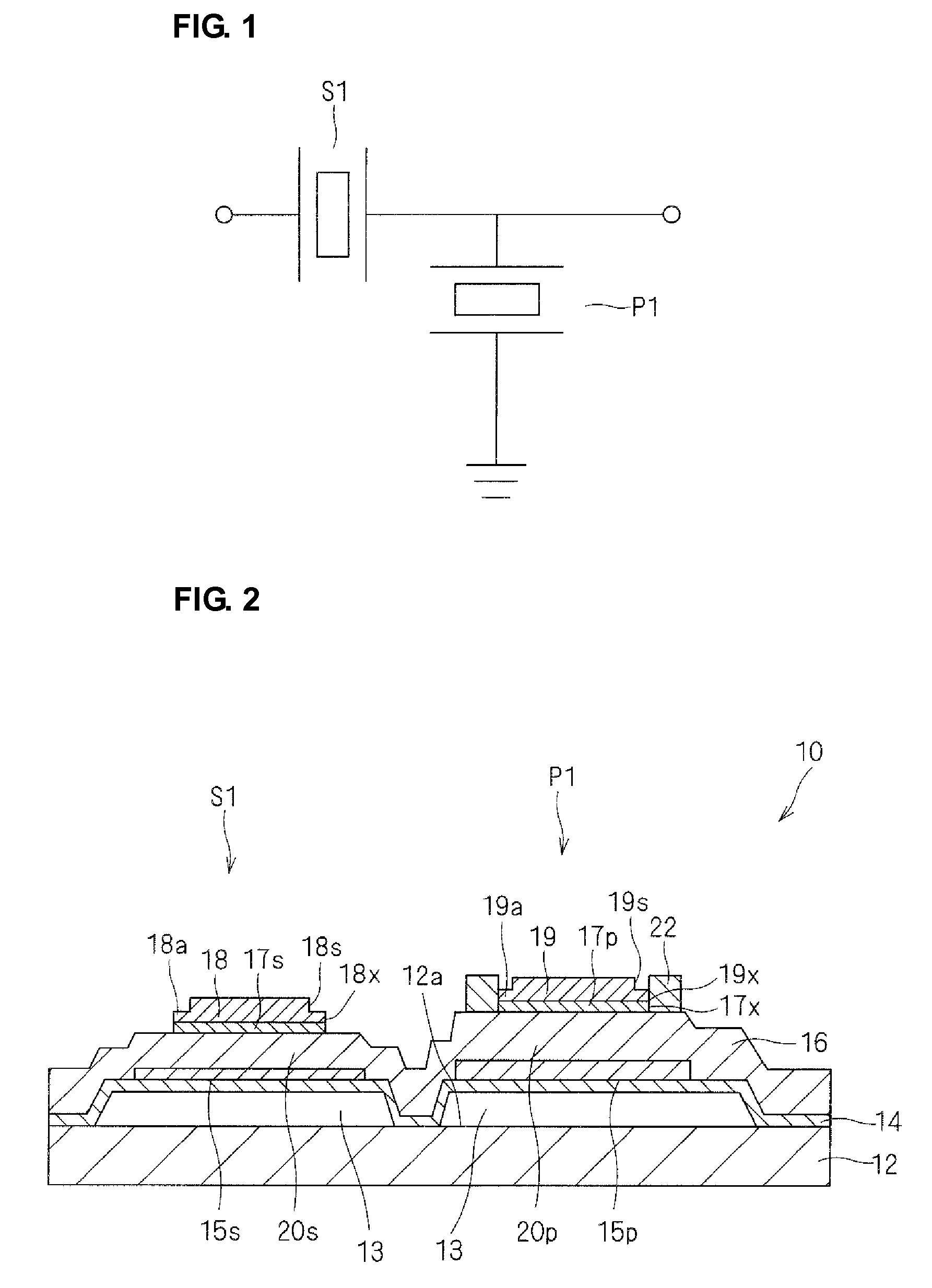
[0062]As shown in a circuit diagram of FIG. 1, the piezoelectric thin-film filter 10 according to the first preferred embodiment includes a ladder-type filter(s) including a series resonator S1 and a parallel resonator P1 and provided in one or two or more stages.

[0063]That is, in the piezoelectric thin-film filters 10, using the one stage shown in FIG. 1 as a basic unit, the ladder-type filters are provided in multiple stages and cascade-connected as necessary in accordance with the specification. An inductor may be connected to a resonator in series.

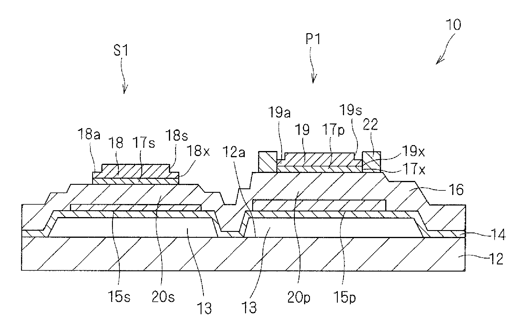
[0064]The series resonator S1 and parallel resonator P1 are configured as shown in a sectional view of FIG. 2.

[0065]A supporting layer 14, lower electrodes 15s and 15p, a piezoelectric thin film 16, upper electrodes 17s and 17p, frequency adjustment films 18 and 19, and an additional film 22 are lamina...

second preferred embodiment

[0096]As with the filter according to the first preferred embodiment, a filter according to the second preferred embodiment is a one-stage or multiple-stage, ladder-type filter formed by combining a type A resonator and a type B resonator.

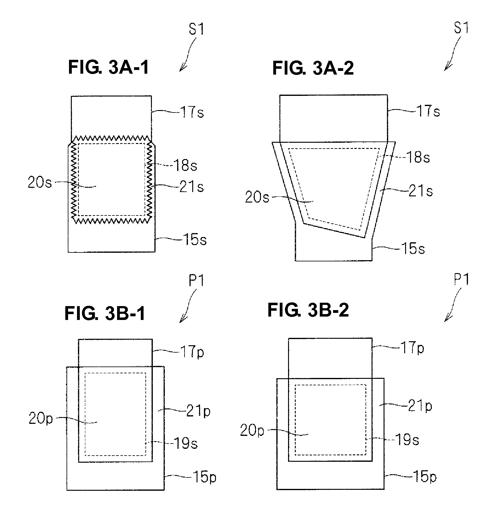
[0097]The filter according to the second preferred embodiment uses a type A resonator including a vibration portion, a plan view shape of which is an asymmetrical polygon shown in FIG. 3A-2 and a type B resonator including a vibration portion, a plan view shape of which is a square shown in FIG. 3B-2. As with the first preferred embodiment, the second preferred embodiment uses a type A resonator as the series resonator S1 having a resonator capacitance smaller than the reference value (e.g., about 1.2 pF) and a type B resonator as the parallel resonator P1 having a resonator capacitance larger than the reference value (e.g., about 1.2 pF).

[0098]As shown in Table 2 below, the filter according to the second preferred embodiment is different from the ...

third preferred embodiment

[0100]A filter according to the third preferred embodiment will be described with reference to FIGS. 7 to 8.

[0101]As shown in a circuit diagram of FIG. 7, the filter according to the third preferred embodiment preferably is a three-stage, ladder-type filter including series resonators S1 to S4 and parallel resonators P1 to P3. As with the filter according to the first preferred embodiment, the three-stage, ladder-type filter is formed by combining type A resonators and type B resonators. That is, the filter according to the third preferred embodiment uses type A resonators including a vibration portion, a plan view shape of which an asymmetrical polygon shown in FIG. 3A-2 and type B resonators including a vibration portion, a plan view shape of which is a square shown in FIG. 3B-2.

[0102]The resonators S1 to S4 and resonators P1 to P3 are disposed as shown in a layout diagram of FIG. 8. In particular, by combining the resonators S1 to S4 and P1 to P3 each including a vibration portio...


PUM


Abstract

A piezoelectric thin-film filter reduces insertion loss and deterioration of steepness of a shoulder characteristic and reduces the ripple in the passband. In a first vibration portion, a piezoelectric thin film is disposed between a pair of electrodes along one main surface of a substrate. In a second vibration portion, the piezoelectric thin film is disposed between a pair of electrodes along the one main surface of the substrate. The vibration portions are both acoustically isolated from the substrate. In the first resonator, an additional film is disposed outside the electrode constituting half or more the overall length of the perimeter of the first vibration portion that is in contact with the electrode when seen from a thickness direction. In the second resonator, the external shape of the vibration portion when seen from a thickness direction is a polygon, and each side of the polygon is not parallel with any of the other sides thereof.

Description

BACKGROUND OF THE INVENTION[0001]1. Field of the Invention[0002]The present invention relates to a piezoelectric thin-film filter, more specifically, a piezoelectric thin-film filter where a vibration portion in which a piezoelectric thin film is interposed between a pair of electrodes is supported in such a manner that the vibration portion is acoustically isolated from a substrate.[0003]2. Description of the Related Art[0004]There have been proposed various configurations to improve characteristics of a piezoelectric thin-film filter where a vibration portion in which a piezoelectric thin film is interposed between a pair of electrodes is supported in such a manner that the vibration portion is acoustically isolated from a substrate.[0005]For example, Japanese Unexamined Patent Application Publication No. 2000-332568 proposes that in order to restrain irregular vibration generated in a lateral resonance mode, an electrode be formed as shown in a plan view of FIG. 27 so that the ex...

Claims


Application Information

Patent Timeline
Patent Type & Authority Applications(United States)
IPC IPC(8): H03H9/54H03H9/17
CPCH03H9/0095H03H9/0211H03H9/02118H03H9/132H03H9/568H03H9/174H03H9/175H03H9/564H03H9/173
Inventor UMEDA, KEIICHI
Owner MURATA MFG CO LTD
Why Eureka
Try Eureka