

Resonator, filter, duplexer, and communication device
a communication device and filter technology, applied in the direction of resonators, superconductors/hyperconductors, waveguides, etc., can solve the problems of power loss, micro-strip lines suffer from degradation of their characteristics,
- Summary
- Abstract
- Description
- Claims
- Application Information
AI Technical Summary
Benefits of technology
Problems solved by technology
Method used
Image

Examples
first embodiment
[0054] A resonator according to the present invention is described with reference to FIGS. 1 to 7.
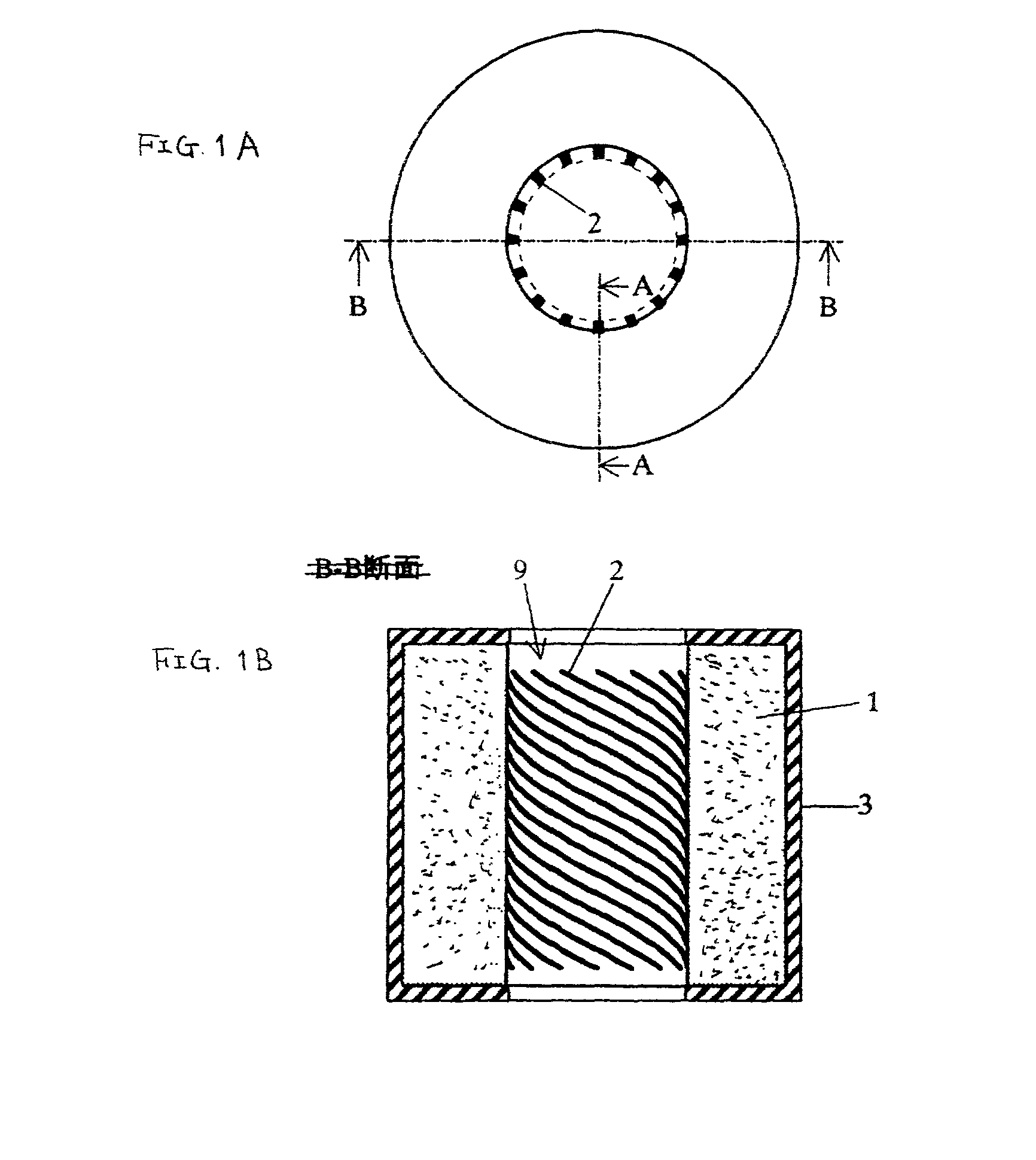
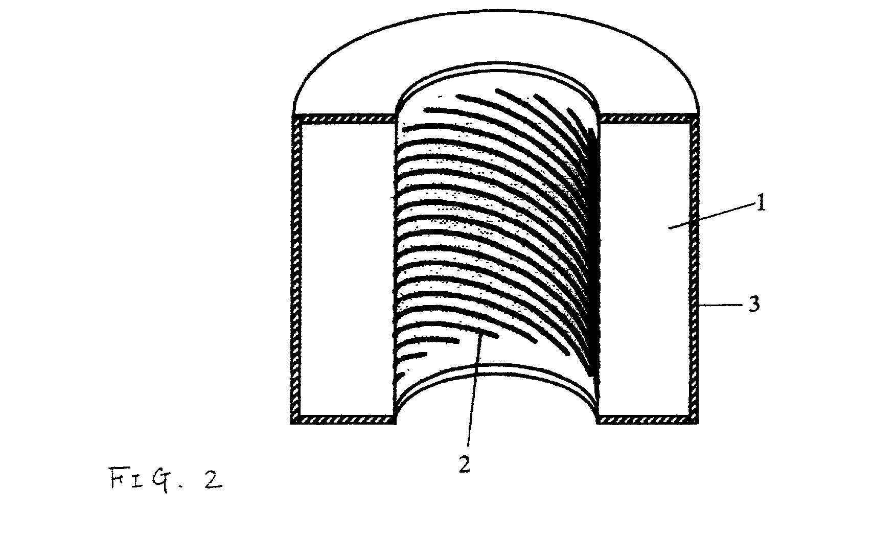
[0055] FIGS. 1A and 1B are a top plan view and a cross-sectional view of a resonator according to the first embodiment. FIG. 2 is a cut-away perspective view thereof.
[0056] In the illustrated example, a hollow cylindrical dielectric element 1 has a hole 9. A plurality of helical lines 2 are formed in the hole 9, and a ground electrode 3 is formed on the outer surface of the dielectric element 1. Each of the helical lines 2 serves as a half-wave resonant line having open ends, and adjacent helical lines are coupled to each other by mutual induction and capacitance. The helical lines collectively form a single helical line unit, which becomes a central conductor of a coaxial resonator. A resonator of this type thus includes a central conductor formed of a multiple helical line unit and having open ends, wherein predetermined stray capacitance is generated between the open ends and the gro...
second embodiment
[0076] A resonator according to the present invention is now described with reference to FIGS. 8A to 8C and 9.
[0077] FIG. 8A is a front view of the resonator. FIGS. 8B and 8C are cross-sectional views of the resonator taken along the lines A-A and B-B of FIG. 8A, respectively. FIG. 9 is a perspective view of the resonator.
[0078] In the illustrated example, a plurality of helical lines 2, which form a multiple helical line unit, are arranged on a surface of a cylindrical dielectric element 1. Each of the helical lines 2 serves as a half-wave resonant line having open ends, and adjacent helical lines are coupled to each other by mutual induction and capacitance. The helical lines collectively form a single inner conductor, which becomes a central conductor of a coaxial resonator.
[0079] In FIGS. 8A to 8C, the cylindrical dielectric element 1 is employed as a base on which the helical lines 2 are formed. However, the base may be replaced by an insulator or a magnetic element.
third embodiment
[0080] FIGS. 10A to 10C show a resonator according to the present invention. A resonator of this type includes a resonator element having the same configuration as in FIGS. 8A to 8C, and disc-shaped conductive shielding plates 4' which are laid over the upper and lower surfaces of the cylindrical dielectric element 1. There is a predetermined space between the conductive shielding plates 4' and the open ends of each helical line 2. FIG. 10C is a cross-sectional view of the resonator taken along the line B-B of FIG. 10A, and shows the electromagnetic field distribution thereof. The electromagnetic field generated by the helical lines 2 is shielded by the conductive shielding plates 4' so that unwanted emission to the outside and unwanted coupling to the outside are prevented.
[0081] FIGS. 11A to 11C show a resonator according to a fourth embodiment of the present invention. This resonator is of the type in which a resonator element having the same configuration as in FIGS. 8A to 8C is...
PUM
| Property | Measurement | Unit |
|---|---|---|
| electric current | aaaaa | aaaaa |
| width | aaaaa | aaaaa |
| width | aaaaa | aaaaa |
Abstract
Description
Claims
Application Information