Power factor correction converter capable of fast adjusting load

a technology of power factor and converter, applied in the direction of electrical energy, process and machine control, instruments, etc., can solve the problems of ineffective improvement of power factor, high total harmonic distortion of input current, and high physical volume, so as to enhance the capability of system controlling load disturban

Inactive Publication Date: 2010-12-02
RHYMEBUS CORP
View PDF2 Cites 22 Cited by
  • Summary
  • Abstract
  • Description
  • Claims
  • Application Information

AI Technical Summary

Benefits of technology

[0018]C. In order to solve the defects of dynamic response of prior art, a powerful controller design is provided in this invention to enhance the capability of system controlling the load disturbance in that when the DC output terminal is connected to a fast variation load, such as a motor driver, a required stable DC output voltage may be supplied. In this invention, an adequate transient comp

Problems solved by technology

However, in such a manner, the total harmonic distortion of input current is high, the physical volume is extremely high, and the power factor is not effectively improved.
However, there are many defects in the conventional correction circuit, such as what is described below.(A) Being implemented with hardware, the structural control circuit is easily limited to the characteristics of all circuit components, and errors caused in a manufacturing process, so it is not easy to implement the control strategy.(B) With reference to FIG. 4, because the sine current command is obtained according to the input voltage signal B detected by the resistor 23, when the voltage of input power 26 forms a non-pure sine wave, if the current command W4 is applied in this case, harmonic content is contained; thus, the current of real input power 26 and the identical harmonic content of input voltag

Method used


Image

  • Power factor correction converter capable of fast adjusting load
  • Power factor correction converter capable of fast adjusting load
  • Power factor correction converter capable of fast adjusting load

Examples


Embodiment Construction

[0031]Now, the present invention will be described more specifically with reference to the following embodiments. It is to be noted that the following descriptions of preferred embodiments of this invention are presented herein for purpose of illustration and description only; it is not intended to be exhaustive or to be limited to the precise form disclosed.

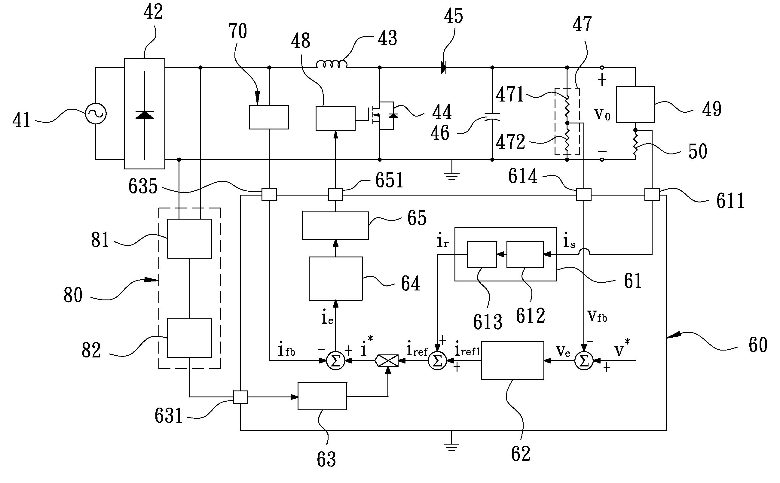
[0032]With reference to FIG. 6 shown as a schematic view illustrating a circuit in a preferred embodiment of this invention, the structure according to this invention is a booster-based AC-DC converter. The circuit comprises at least one input power 41, one rectifier 42, one power factor correction component 43, one power switch 44, one diode 45, one energy-saving component 46, one voltage sensor unit 47, and a gate driver 48. In the preferred embodiment of this invention, the rectifier 42 is a diode-based bridge rectifier, the power factor correction component 43 is a capacitor, and the voltage sensor unit 47 comprises two pote...


PUM


Abstract

A power factor correction converter capable of fast adjusting load functions to (a) convert a single-phase AC voltage into a DC voltage output; (b) control an input current and an input voltage for a correspondent electrical phase, namely the power factor that is 1; and (c) control a DC output voltage level. The converter is provided with a booster-based AC-DC converter as a core, in which the circuit includes a rectification circuit, a switching circuit consisting of a DC inductor and a power crystal, an energy-saving capacitor, a protection circuit, a microprocessor, and auxiliary circuits around. The power factor control, output voltage, and current control and filter modules function in the form of software program instead of conventional hardware circuits. Further, a powerful controller uses an output current feedback to enhance the DC output voltage to suppress the disturbance of load.

Description

BACKGROUND OF THE INVENTION[0001]1. Field of the Invention[0002]This invention relates to a power factor correction converter capable of fast adjusting load.[0003]2. Description of the Prior Art[0004]With reference to FIG. 1 shown as a schematic view illustrating a conventional single-phase rectification circuit, a bridge rectification circuit 10 consists of four diodes 11, 12, 13, and 14 that are connected in parallel to an output capacitor C1. An AC power P1 is further connected across the bridge rectification circuit 10. When the AC power P1 is positive, the input current is transmitted through diodes 11 and 13; when the AC power P1 is negative, the input current is transmitted through diodes 12 and 14 and then filtered by the output capacitor C1, a DC power being thereby obtained. Although the structure of rectification circuit is advantageously simplified, the bridge rectification circuit 10 that charges the output capacitor C1 easily causes a very high surge current impacting ...

Claims


Application Information

Patent Timeline
IPC IPC(8): H02M7/04
CPCH02M1/4225H02M2001/0019Y02B70/126Y02P80/112Y02B70/10Y02P80/10H02M1/0019
Inventor CHANG, CHENG-CHINGHUANG, MING-SHILEI, YUE-HUEI
Owner RHYMEBUS CORP
Why Eureka
Try Eureka