Compact microstrip patch antenna

a patch antenna and compact technology, applied in the direction of elongated active element feed, substantially flat resonant elements, resonance antennas, etc., can solve the problems of narrow bandwidth, low efficiency, and low efficiency of conventional microstrip patch antennas, so as to reduce internal losses (q) of the antenna, reduce the effective radiating current path of the patch, and reduce the effect of patch effective siz

Inactive Publication Date: 2009-02-26
MICRO ANT
View PDF3 Cites 27 Cited by
  • Summary
  • Abstract
  • Description
  • Claims
  • Application Information

AI Technical Summary

Benefits of technology

[0009]The perturbations lengthen the effective radiating current path of the patch. Thus, the effective size of the patch may be substantially reduced relative to a given frequency of operation. The perturbations also help decrease internal losses (Q) of the antenna and increase antenna impedance bandwidth. Thus, given a particular operating frequency or wavelength, a microstrip patch antenna according to principles of the invention may have a reduced size as compared to prior conventi

Problems solved by technology

Unfortunately, however, conventional microstrip patch antennas suffer from a number of disadvantages as compared to conventional antennas.
Some of their major disadvantages include narrow bandwidth, low efficiency and low gain.
However, such a configuration leads to a larger antenna size.
To design a compact microstrip patch antenna, higher dielectric constants must be used, which are costly, less efficient, result in narrower bandwidth.
As ετ increases, so do internal losses, which leads to narrow bandwidth and low efficiency.
Con

Method used


Image

  • Compact microstrip patch antenna
  • Compact microstrip patch antenna
  • Compact microstrip patch antenna

Examples


Embodiment Construction

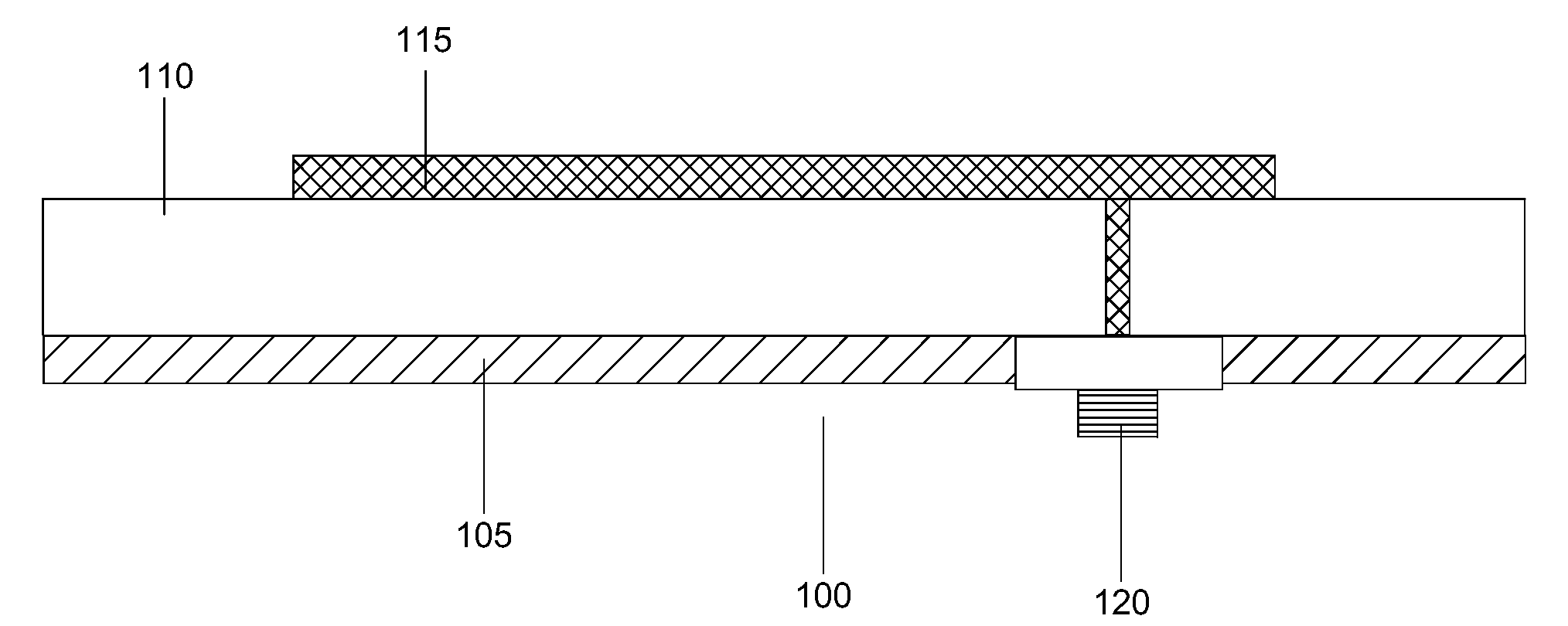
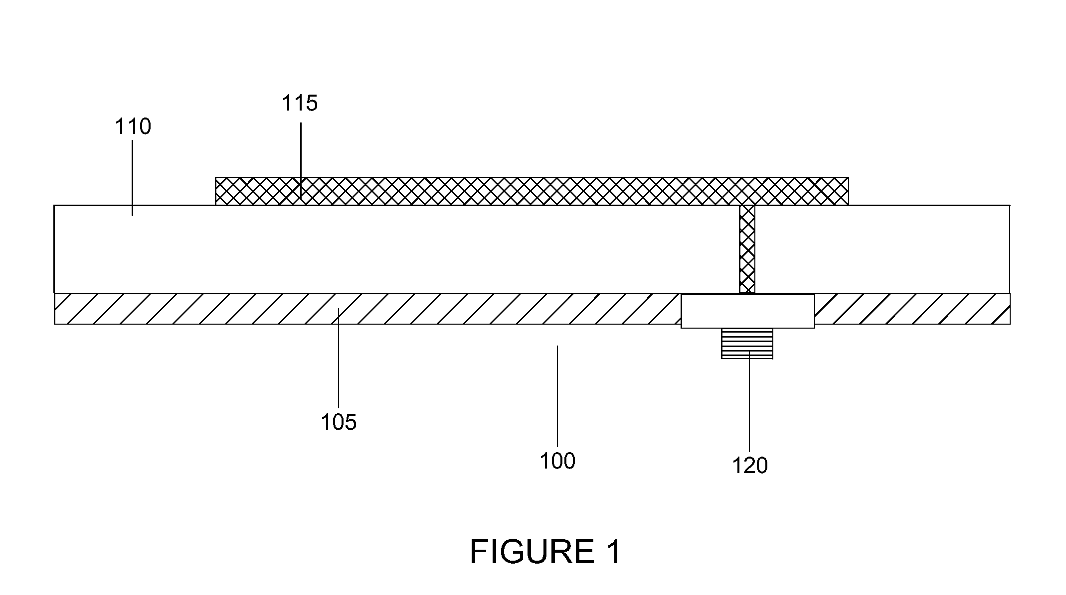
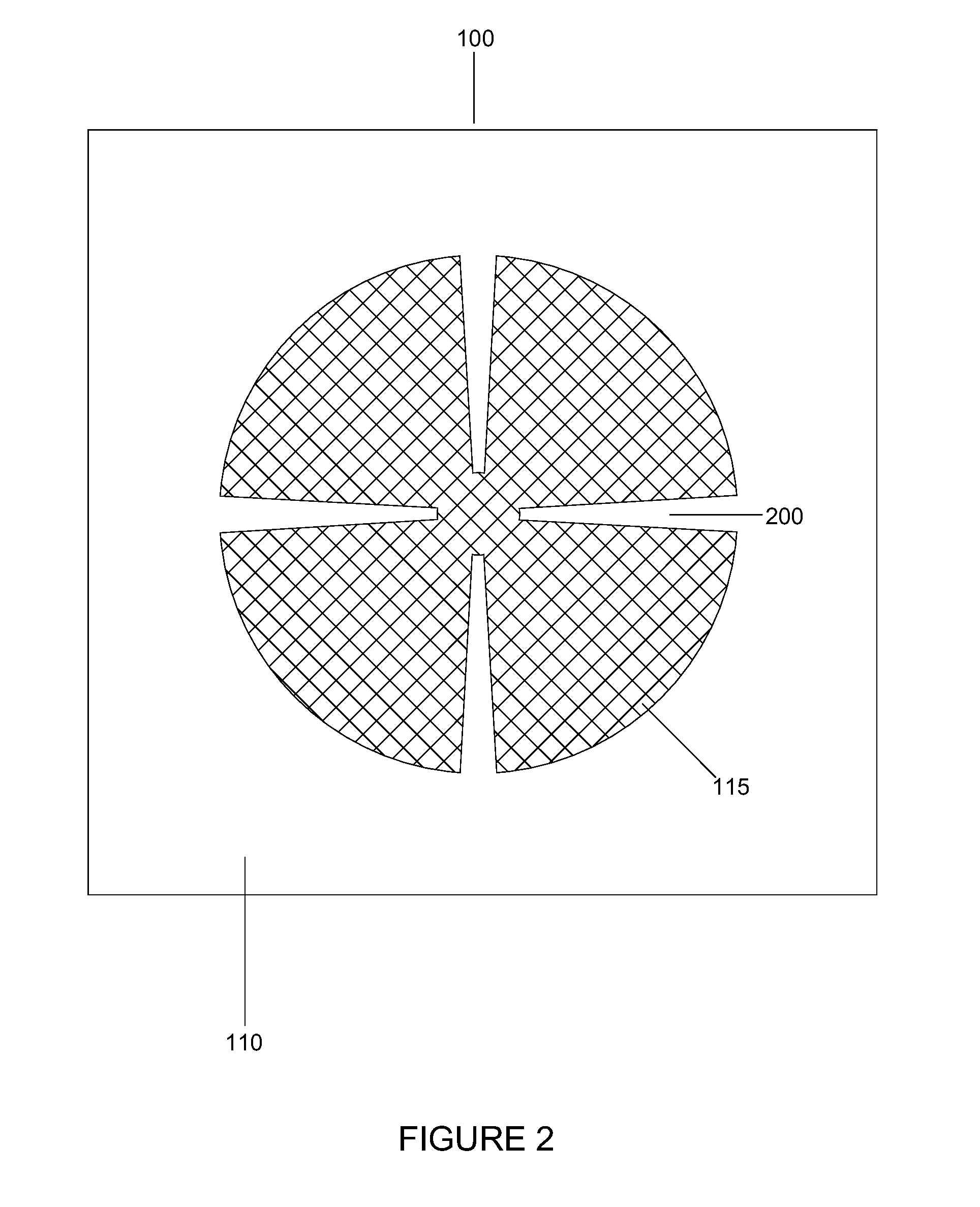
[0021]Referring to FIG. 1, a side sectional view of an exemplary microstrip patch antenna 100 according to principles of the invention is shown. The antenna 100 is comprised of a base conductor layer (the groundplane) 105, a dielectric spacer (the substrate) 110, and a signal conductor layer (the microstrip) 115. The exemplary microstrip 115, which may be fashioned into a circular geometry as illustrated in FIG. 2, is called the “patch”.

[0022]The exemplary microstrip patch antenna 100 may be fed by a variety of devices now known or hereafter developed. Such devices can be classified into two categories-contacting and non-contacting. In a contacting scheme, a connecting element, such as a microstrip line or coaxial connector 120 (as shown in FIG. 1), couples the groundplane 105 and patch 115. The inner conductor of the coaxial connector 120 may extend through the dielectric and connect to the radiating patch, while the outer conductor may be connected to the ground plane 105. In a no...


PUM


Abstract

A microstrip patch antenna includes a plurality of radially extending perturbations about the perimeter of the patch. The flow of electromagnetic current progressing along the perimeter of the patch is perturbed and results in an effective electromagnetic diameter substantially greater than the actual physical diameter of the patch.

Description

FIELD OF THE INVENTION[0001]This invention generally relates to microstrip patch antennas and, more particularly, to a method for making such antennas substantially smaller with marginal compromise to overall performance by introducing a plurality of converging perturbations about the perimeter of the patch so that the flow of electromagnetic current progressing along the perimeter of the patch is perturbed and results in an effective electromagnetic diameter substantially greater than the actual physical diameter of the patch.BACKGROUND[0002]Microstrip patch antennas are increasing in popularity for use in wireless applications due to their low-profile, light weight and low volume configuration which can be easily made to conform to a host surface. Other principal advantages include low fabrication cost and support for both linear and circular polarization. A typical microstrip patch antenna is comprised of three components: a base conductor layer (the groundplane), a dielectric sp...

Claims


Application Information

Patent Timeline
IPC IPC(8): H01Q9/04H01Q1/38
CPCH01Q1/243H01Q9/42H01Q9/0407H01Q1/38
Inventor MCCARRICK, CHARLES DAVIDPOE, GREG C.
Owner MICRO ANT
Why Eureka
Try Eureka